XBee surface-mount (SMT) Grove development board
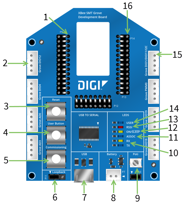
This picture shows the XBee SMT Grove development board and the table that follows explains the callouts in the picture.
| Number | Item | Description |
|---|---|---|
| 1 | SMT XBee socket | |
| 2 | Grove connectors | The board provides eight vertical Grove connectors connected to XBee DIO lines. |
| 3 | Reset button | Button connected to the XBee reset pin. |
| 4 | User button | Button connected to the XBee DIO4 line. The button shares the same DIO line with one user LED. |
| 5 | Commissioning button | Button connected to the XBee commissioning pin. |
| 6 | Loopback jumper | Three-pin jumper to connect the UART to the USB (normal mode) or to make a loopback connection between the Rx and Tx signals of the UART. |
| 7 | Micro USB | The XBee serial port is connected through a USB to RS-232 converter to a micro USB connector provided on the board. |
| 8 | Battery connector | Two-pin, 2 mm pitch, PH type connector from JST to power the board from an external battery. |
| 9 | Potentiometer | 10 K potentiometer connected to the XBee AD3 line. One jumper is available to save power when it is not used. |
| 10 | RX and TX indicators |
Yellow: UART Rx / RF Tx Blue: UART Tx / RF Rx |
| 11 | Association indicator | LED connected to the XBee association pin. |
| 12 | ON/SLEEP LED |
LED connected to the ON/SLEEP pin (DIO9). On: XBee is awake Off: XBee is asleep |
| 13 | RSSI indicator | LED connected to the XBee RSSI pin. |
| 14 | I2C bus | Bus connected to XBee DIO1/DIO19, to be used with several Grove sensors. |
| 15 | User LED | Shares DIO4 with the user button. |
| 16 | Test points |
 PDF
PDF


