XBIB-U-DEV reference
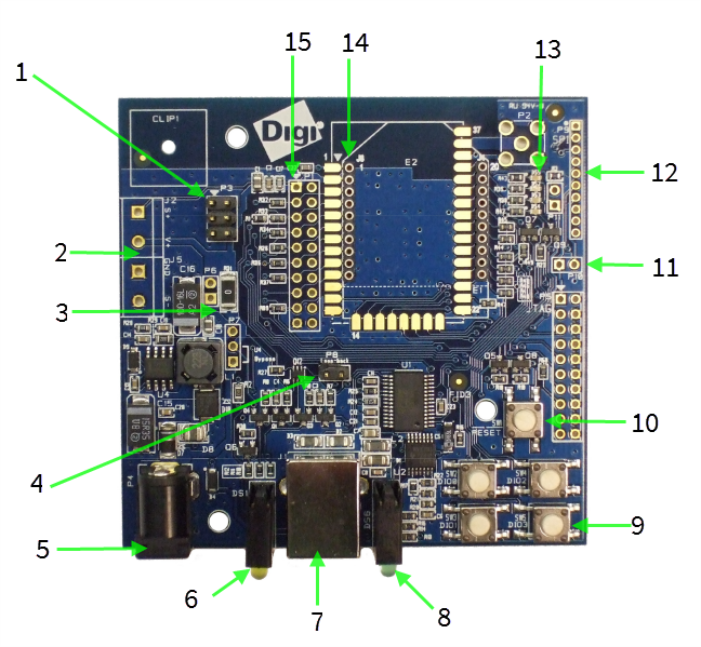
This picture shows the XBee USB XBIB-U-DEV development board and the table that follows explains the call-outs in the picture.
| Number | Item | Description |
|---|---|---|
| 1 | Programming header | Header used to program XBee programmable devices. |
| 2 | Self power module |
Advanced users only—voids the warranty. Depopulate R31 to power the device using V+ and GND from J2 and J5. You can connect sense lines to S+ and S- for sensing power supplies. |
 CAUTION: Voltage
is not regulated. Applying the incorrect
voltage can cause fire and serious
injury.1 CAUTION: Voltage
is not regulated. Applying the incorrect
voltage can cause fire and serious
injury.1 |
||
| 3 | Current testing | Depopulating R31 allows a current probe to be inserted across P6 terminals. The current though P6/R31 powers the device only. Other supporting circuitry is powered by a different trace. |
| 4 | Loopback jumper | Populating P8 with a loopback jumper causes serial transmissions both from the device and from the USB to loopback. |
| 5 | DC barrel plug: 6-20 V | Greater than 500 mA loads require a DC supply for correct operation. Plug in the external power supply prior to the USB connector to ensure that proper USB communications are not interrupted. |
| 6 | LED indicator |
Yellow: Modem sending serial/UART data to host. Green: Modem receiving serial/UART data from host. Red: Associate. |
| 7 | USB | Connects to your computer. |
| 8 | RSSI indicator |
See RSSI PWM. On the XBIB-U, more lights are better. |
| 9 | User buttons | Connected to DIO lines for user implementation. |
| 10 | Reset button | Press the reset button to reset the device to the default configuration. |
| 11 | SPI power | Connect to the power board from 3.3 V. |
| 12 | SPI | Only used for surface-mount devices. |
| 13 | Indicator LEDs |
DS5: ON/SLEEP DS2: DIO12, the LED illuminates when driven low. DS3: DIO11, the LED illuminates when driven low. DS4: DIO4, the LED illuminates when driven low. |
| 14 | Through-hole XBee sockets | |
| 15 | 20-pin header | Maps to standard through-hole XBee pins. Male, Samtec header, part number: TSW-110-26-L-D. 2.54 mm / .100" pitch and row spacing. |
 PDF
PDF


