XBEE sensors
Product description
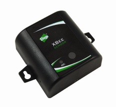
The XBee Sensor provides real-time data on temperature, humidity, and light, with the data being transmitted through wireless communications in an XBee network infrastructure. Compact size and battery power enable XBee Sensors to be dropped into facilities easily and unobtrusively while providing reliable communications. Applications include building automation, environmental monitoring, security, asset monitoring, and more.
The readings are of modest accuracy, suitable for environmental monitor but not likely suitable for control systems (See the Accuracy Section below)
There are currently two XBee Sensor product options available:
- XBee Sensor /L/T: Integrated ambient light and temperature sensors
- XBee Sensor /L/T/H: Integrated ambient light, temperature, and humidity sensors
Programming options
There are many options to consider when making wireless programmatic access to an XBee network of devices or device adapters. In broad terms, one may write a program which runs on a PC to interact with a network or one may use a gateway device, such a ConnectPort X [2] gateway.
When using a PC, one may consider using the simplistic and easy "AT-Command" mode for the XBee attached to the computer. Although using this mode is straight-forward it does not offer one as fine of control as when using the "API mode" firmware option.
One may also consider using a Digi ConnectPort X family of gateway device to provide additional intelligence and flexibility when connecting to a network of wireless devices. The ConnectPort X [3] offers a customizable Digi Python Programmers Guide and instant connectivity to the Device Cloud Management Platform. The ConnectPort X offers users the ability to choose to write their own applications from the ground-up, using Digi's and Python's[4] reference and example information, or to use the highly extensible DIA Application to collect and aggregate information.
iDigi Dia configuration and programming examples
Python programming examples
Configuration settings
During system start up or configuration, you require:
- D1, D2 and D3 should be set to 2, enabling analog input to the 3 sensors.
- DH and DL should be set to your XBee coordinator (your CPX gateway) or the XBee device to receive the data productions.
- P1 (DIO11) should be set to 3, enabling digital input on the battery monitor pin.
Operational settings
Although you can poll the XBee Sensors, this requires the XBee to be awake most of the time and you battery life will be limited to a few months. You may find having it wake once per 10 or 15 minutes the best solution.
The assumed operation is to place the XBee Sensor into sleep, then have it send the data unsolicited to the XBee node listed in the DH/DL settings.
To enable sleeping operation longer than 1 minute:
- Set IR to 0xFFFF, which effectively disables the 'sample rate' setting.
- Set WH to 125 to allow the sensor hardware to stabilize for 125msec before the XBee reads the analog inputs (note: not all XBee modules support the WH parameter)
- Set the SN/SP pair to enable sleeping for the desired time period.
- SP is the number of 10msec periods to sleep
- SN is the number of SP-periods to sleep for.
- For example, SP=2000 and SP=30 leads to an approximately 600 seconds data productions (30 x 20 second periods or 10 minutes).
- The SN/SP within your gateway and all XBee routers MUST be at least as large as the values placed into the XBee Sensor product, or you will find the routers (the parents) de-associate the sleeping XBee Sensor (the child) while it sleeps, and thus reject the periodic data productions.
Formulas
Temperature:
temp_C = (mVanalog - 500.0)/ 10.0
mVanalog = (ADC2/1023.0) * 1200
Humidity:
hum = (((mVanalog * 108.2 / 33.2) / 5000 - 0.16) / 0.0062)
mVanalog = (ADC3/1023.0) * 1200
Light:
brightness = (ADC1) /1023.0) * 1200
Hardware information
Power options
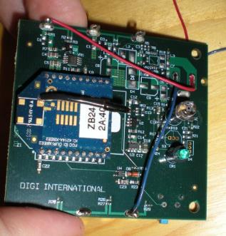
Although it is designed to run on 3 AA batteries, it can operated on any stable voltage supply from about 3.6v up to 6.0v. For testing purposes you can use a stable 5vdc supply, attaching your power leads to the battery tabs as shown in the photo (red is +, blue is -). The wires pass through, but do not connect to the barrel jack socket-holes. This jack is only connected electronically in the 9-30vdc version of this PCB (which is not available).
XBee module support
The XBee L/T/H/ Sensor requires either the 'End Device AT' or 'Router AT' firmware on the XBee. Although it is designed to run on 3 AA batteries, it can operated on any stable voltage supply from about 3.7v up to 6.0v. For testing purposes, you can use a stable 5VDC supply.
Given the need to be low power and to sleep, not all XBee modules are appropriate for this product.
| Module | Description | Tested | Comments | Firmware | /L/T DD Value | /L/T/H DD Value |
|---|---|---|---|---|---|---|
| XB24-A | 802.15.4 on 2.4Ghz | Pending | ||||
| XB24-B | ZNet 2.5 on 2.4Ghz | Yes | ZNet 2.5 Router/End Device AT, such as 1247 | 0x2000E | 0x2000D | |
| XB24-ZB | Zigbee 2007 on 2.4Ghz | Yes | Zigbee End Device AT, such as 2864 | 0x3000E | 0x3000D | |
| XB09-DM | DigiMesh on 900Mhz | Pending | ||||
| XB24-DM | DigiMesh on 2.4Ghz | Pending | ||||
| XB08-DP | Point-to-Multipoint on 868Mhz | No | Consumes too much power | N/A | N/A | |
| XB09-DP | Point-to-Multipoint on 900Mhz | Pending |
Notes:
Although the XBee XB24-ZB family includes a firmware named "Zigbee Router/End Device Sensor", that firmware is for the 1-wire Sensor Adapter - it is not for the Sensor /L/T or /L/T/H. Installing this firmware will result in bad values being read.
Accuracy
XBee L-T-H sensor adapter
The /L/T/H product is not calibrated by Digi. This means multiple units placed side-by-side out of the box will show a higher than desired variability. However, the sensor readings are fairly linear and modest software calibration can greatly improve the accuracy.
Temperature
The stated accuracy per the datasheet (and component supplier) is +/- 2 DegC (+/- 3.6 DegF).
They are not designed for industrial control, and even the temperature within a normal room varies by many degrees based on drafts, heat or cold sources, and how far the sensor is above the floor. Anyone who looks at a thermostat, reads the '72' and believes the entire room is a perfectly constant 72 degrees Fahrenheit is being foolish.
Ad-hoc tests show that a simple fixed offset added or subtracted to the readings allow them to be used in normal building automation with satisfactory result. For example, a test of four units showed that adding constants to the raw 0-1023 value allowed all four to return the same temperature to within +/- 0.25 DegC most of the time and to within +/- 0.75 DegC all of the time. The magnitude of these binary constants within this test of four units were (-4, 14, -15 and 5). You could use a float constant scaled as DegC or DegF instead.
These constants were calculated by taking 5 readings over five hours, then examining the average deviation from the desired value. For example, one unit returned the values 739, 735, 734, 700 and 702 when the expected values were 738, 732, 732, 690, and 694. Thus adding a -4 (subtracting 4) from the value received resulted in a better value. The expected value was calculated based on the temperature reading of a third party device 'trusted' as correct.
Humidity
The stated accuracy per the datasheet (and component supplier) is:
Interchangeability: +/- 5 %RH (0%RH to 59%RH) and +/- 8 %RH (60%RH to 100%RH)
Accuracy: +/- 3.5%RH
This means if you take a dozen factory-fresh units, allow them to stabilize within a 70%RH environment, then you may see readings range from 62%RH to 78%RH. This is the ‘Interchangeability’ clause.
However, if the user does modest linear software calibration (primarily fixed offset), then the same dozen devices can show the 70%RH as 66.5%RH to 73.5%RH. This is the ‘Accuracy’ clause.
Light
The light sensor in the adapter returns values from 0 to about 1100 based on light intensity - it does not return any standard measure, and the actual readings vary based on the opacity of the label applied and so on. It can be used to easily sense that a room is brighter or darker. For example, you can use it to turn security lights on when the sun goes down - or to turn off room heaters and computer displays when the overhead lights are turned off, indicating that the room is not occupied.
Note These are simple, low-cost "light intensity" sensors that are intended to be used for a wide variety of applications. However, they were never intended to measure the lux of a particular scene. For this reason, we're not able to provide a formula to convert light intensity to lux.
You could not use it (for example) to test that a workbench has an exact luminous intensity of "X" cd/m2. If you require such measurements, you should use a standard light sensor with a 0-10v or 4-20mA signal in a AIO adpater.
Also note that the duration of the actual light detection is short, so it works best with either sun light or non-flickering incandescent or DC-powered halogen lamps. Measure light with standard fluorescent light will result in the light value varying over a range of values (many percentage points). This does not prevent your system from detection 'the room is light' or 'the room is dark', but you will need to accommodate this variation with a hysteresis or dead-band calculation.
 PDF
PDF


