Adding a custom display
This application note describes the i.MX6 CPU graphical system and the steps to define a new custom TFT (Thin Film Transistor) display panel in Digi Embedded Yocto and discusses the most standard panels available. Some panels may need special consideration.
Introduction
LCD panels
An LCD panel is a matrix of pixels that are divided into rows and columns. These pixels are individually painted according to different signals and timing parameters, and you can control each pixel's color individually. The panel is continuously refreshed, typically at around 60 Hz, from the contents of the frame buffer memory. Each memory location on the frame buffer corresponds to a pixel on the LCD panel.
A 1024 x 600 resolution display requires 614400 memory locations, with each location having a number of possible colors. The number of bits needed to describe the available colors is called bits per pixel (bpp). For example, 16 bpp can describe 65536 colors and 24 bits can describe 16777216 colors (known as true color). A panel with 614400 24-bit locations requires a 1800 KB frame buffer.
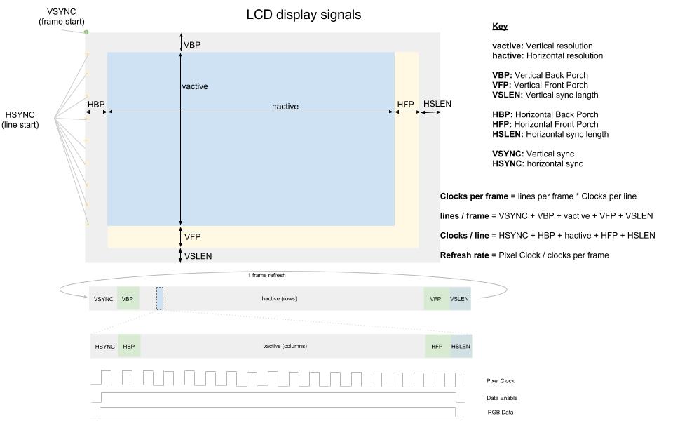
LCD displays signals and timing parameters
The LCD controller paints frames from left to right and from top to bottom. Signals used on a typical LCD display include:
- HSYNC: Horizontal synch (FPLINE or LP) indicates the end of a line and the beginning of the next line.
- VSYNC: Vertical synch (FPFRAME, FLM, SPS or TV) indicates the end of the current frame. The next line index should restart at zero in the upper-left corner.
- DRDY: Data ready or data enable (DE). The data in the bus is valid and must be latched using the PIXCLK signal. While it’s active, each pulse draws a pixel.
- PIXCLK: Specifies the placing of RGB data on the bus.
- RGB data: Red, green, and blue pixel data. Usually 24 data lines for RGB888, 16 data lines for RGB666.
Typical timing parameters include:
- Horizontal Back Porch (HBP): Number of PIXCLK pulses between HSYNC signal and the first valid pixel data.
- Horizontal Front porch (HFP): Number of PIXCLK pulses between the last valid pixel data in the line and the next HSYNC pulse.
- Vertical Back Porch (VBP): Number of lines (HSYNC pulses) from a VSYNC signal to the first valid line.
- Vertical Front Porch (VFP): Number of lines (HSYNC pulses) between the last valid line of the frame and the next VSYNC pulse.
- VSYNC length: Number of HSYNC pulses when a VSYNC signal is active.
- HSYNC length: Number of PIXCLK pulses when a HSYNC signal is active.
- Active frame width (hactive): Horizontal resolution.
- Active frame height (vactive): Vertical resolution.
Every manufacturer provides display timings in a slightly different way and some provide more detail than others. Most LCD panels work with a range of timing parameters.
This application note provides a couple of examples to help you further understand these concepts.
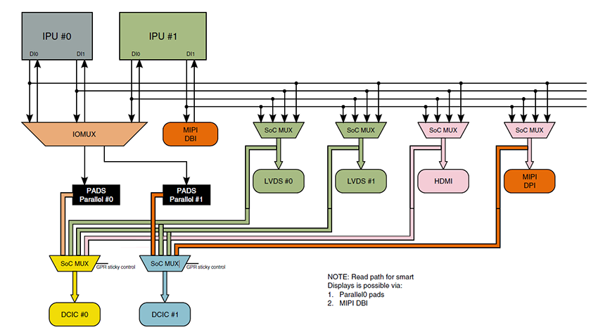
The i.MX6 graphical system
The ConnectCore 6 system-on-module is designed in different module variants with both the i.MX6 Quad/Dual or i.MX6 DualLite/Solo System-On-Chips. The i.MX6 Quad/Dual has two Image Processing Units (IPU0, IPU1), each containing two Display Interfaces (DI0, DI1) while the i.MX6 DualLite/Solo has just one IPU.
This application note focuses on the i.MX6 Quad/Dual, although the concepts apply to the i.MX6 DualLite/Solo as well (except the DualLite/Solo has only one IPU).
Note If you are working on the ConnectCore 6 SBC, the corresponding IOMUX settings for the different interfaces are already configured on DEY. If you are working on a custom carrier board, you must provide the corresponding IOMUX settings on the machine's device tree.
Frame buffer device nodes in Linux
The i.MX6 IPUs define a series of frame buffer devices (/dev/fbN, where N is an index number starting at zero) that correspond to the graphical capabilities of the SoC.
The i.MX6 Dual/Quad has two IPUs, each containing two DIs. Additionally, the driver allows for an overlay frame buffer per IPU (to be displayed over the frame buffer of DI0). These overlay frame buffers are also represented by nodes /dev/fbN.
For example, a system with one HDMI monitor, two LVDS displays, and one parallel LCD display might represent in the Linux system as follows:
- /dev/fb0: HDMI monitor
- /dev/fb1: Overlay for /dev/fb0
- /dev/fb2: Primary LVDS display
- /dev/fb3: Overlay for /dev/fb2
- /dev/fb4: Parallel LCD display
- /dev/fb5: Secondary LVDS display
The index numbers are assigned by the kernel in order of probing of the different drivers, so they may change from system to system.
The i.MX6 graphical system and displays on Linux
Device Tree
Displays are defined on the platform's device tree file. For defining a custom display on the device tree you must have entries for:
- Frame buffers
- Display drivers
- Display timings
Frame buffers
Frame buffer devices provide an abstraction for the graphics hardware. You must create a frame buffer entry on your platform's device tree file and bind it to a graphics driver through the compatible property.
The following example creates a frame buffer and binds it to the MXC frame buffer device driver (drivers/video/mxc/mxc_ipuv3_fb.c).
Frame buffer node binding to MXC graphics driver
mxcfb1: fb@0 {
    compatible = "fsl,mxc_sdc_fb";
};
The driver's binding documentation at Documentation/devicetree/bindings/fb/fsl_ipuv3_fb.txt describes additional properties for the frame buffer. You must complete the node with required and optional properties that match your hardware, for example:
- Frame buffer on MXC graphics driver
- HDMI display
- Pixel format RGB24
- Video mode string ("1920x1080M@60" for HDMI, as per bindings documentation)
- Default bits per pixel: 32
- Do not use internal clock for pixel clock
- No late init
MXC frame buffer on HDMI, RGB24, 1920x1080 resolution at 60MHz, 32 bits per color, use internal clock as pixclk
mxcfb1: fb@0 {
    compatible = "fsl,mxc_sdc_fb";
    disp_dev = "hdmi";
    interface_pix_fmt = "RGB24";
    mode_str ="1920x1080M@60";
    default_bpp = <32>;
    int_clk = <0>;
    late_init = <0>;
    status = "okay";
};
You can create as many frame buffer entries as you have available display interfaces in your platform. For example, the i.MX6 Dual/Quad has two IPUs, each containing two display interfaces, equaling a total of four displays:
- Four frame buffers on MXC graphics driver
- One HDMI display
- Two LVDS displays
- One LCD display
Frame buffer device tree nodes (some properties omitted for clarity)
mxcfb1: fb@0 {
     compatible = "fsl,mxc_sdc_fb";
     disp_dev = "hdmi";
     ...
};

 mxcfb2: fb@1 {
     compatible = "fsl,mxc_sdc_fb";
     disp_dev = "ldb";
     ...
};

 mxcfb3: fb@2 {
     compatible = "fsl,mxc_sdc_fb";
     disp_dev = "lcd";
     ...
};

 mxcfb4: fb@3 {
     compatible = "fsl,mxc_sdc_fb";
     disp_dev = "ldb";
     ...
};
Display drivers
The MXC graphics driver uses three different display drivers:
- hdmi for HDMI displays (drivers/video/mxc/mxc_hdmi.c)
- ldb for LVDS displays (drivers/video/mxc/ldb.c)
- lcd for parallel LCD displays (drivers/video/mxc/mxc_lcdif.c)
Note LDB stands for LVDS Display Bridge, which is the interface of the i.MX6 CPU that connects the IPU to an external LVDS display interface.
The driver's binding documentation at Documentation/devicetree/bindings/fb/fsl_ipuv3_fb.txt describes the properties of different display drivers.
For example, the LVDS display bridge (LDB) routing IPU1:DI0 to LVDS channel 0 can be defined as follows:
&ldb {
    status = "okay";

    lvds-channel@0 {
        crtc = "ipu1-di0";
        fsl,data-mapping = "spwg";
        fsl,data-width = <18>;
        primary;

        display-timings {
            [...]
        };
    };
};
Note You can configure the LVDS display bridge for different modes (separate 0 mode on the above example). Refer to the driver's binding documentation at Documentation/devicetree/bindings/fb/fsl_ipuv3_fb.txt and to the i.MX6 CPU reference manual for details about the different supported modes.
Display timings
LCD displays must be created as nodes in the device tree with a display-timings subnode. Display timings binding documentation at Documentation/devicetree/bindings/video/display-timing.txt explains the required timing properties to describe an LCD.
lcdname {
        display-timings {
                timing {
                        clock-frequency = <hz>;
                        hactive = <px>;
                        vactive = <px>;
                        hfront-porch = <px>;
                        hback-porch = <px>;
                        hsync-len = <px>;
                        vback-porch = <lines>;
                        vfront-porch = <lines>;
                        vsync-len = <lines>;
                };
         };
};
Look for these values on your LCD display's datasheet.
The same applies for LVDS displays on LDB, except the display-timings node must be a subnode of the lvds-channel:
&ldb {
    status = "okay";

    lvds-channel@0 {
        fsl,data-mapping = "spwg";
        fsl,data-width = <18>;
        display-timings {
            native-mode = <&timing0>;
            timing0: hsd101pfw2 {
                clock-frequency = <45000000>;
                hactive = <1024>;
                vactive = <600>;
                hfront-porch = <0>;
                hback-porch = <0>;
                hsync-len = <176>;
                vback-porch = <0>;
                vfront-porch = <0>;
                vsync-len = <25>;
            };
        };
    };
};
Adding a custom LCD display
Example 1: Fusion 10.1'' LVDS display
Digi Embedded Yocto for the ConnectCore 6 SBC platform supports the Fusion 10.1" LVDS display out of the box. This section describes how this display was added so that you can use it as reference for similar displays.
Frame buffer
Let's say you want to use the Fusion 10.1" LVDS display on frame buffer 0:
- The frame buffer uses the ldb driver, as it is an LVDS display.
- The Fusion 10" datasheet defines the pixel format as RGB666.
Define frame buffer 0 in your platform's device tree:
Fusion 10.1" on frame buffer 0
mxcfb1: fb@0 {
        compatible = "fsl,mxc_sdc_fb";
        disp_dev = "ldb";
        interface_pix_fmt = "RGB666";
        default_bpp = <16>;
        int_clk = <0>;
        late_init = <0>;
        status = "okay";
};
Display driver
LVDS displays use the ldb driver. For example, you want to use IPU1:DI0 on LVDS channel 0 for this display:
- LVDS channel 0 uses DI0 of IPU1.
- Mode is single (neither dual nor split).
- Data mapping for this display is SPWG.
- Data width is 18 bits.
LVDS channel 0 will be the primary LVDS channel.
Define ldb node in your platform's device tree:
ldb@020e0000 {
        status = "okay";

        lvds-channel@0 {
            crtc = "ipu1-di0";
            fsl,data-mapping = "spwg";
            fsl,data-width = <18>;
            primary;
            status = "okay";
        };
};
Display timings
The Linux kernel requires the following LCD interface timing parameters, as supplied by the Fusion 10 Product Specification:
| Item | Symbol | Min. | Typ. | Max. | Unit |
|---|---|---|---|---|---|
| Frame rate | - | 55 | 60 | 65 | hz |
| Frame period | t1 | 612 | 625 | 638 | line |
| Vertical display time | t2 | 600 | 600 | 600 | line |
| Vertical blanking time | t3 | 12 | 25 | 38 | line |
| One-line scanning time | t4 | 1160 | 1200 | 1240 | clock |
| Horizontal display time | t5 | 1024 | 1024 | 1024 | clock |
| Horizontal blanking time | t6 | 136 | 176 | 216 | clock |
| Clock rate | t7 | 39 | 45 | 51.42 | MHz |
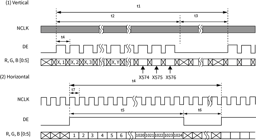
With the information on the datasheet you must fill in the display-timings property of your display node in the device tree. This example uses the values on the typical column:
- clock-frequency is the pixel clock in Hz. On the table, this is the Clock Rate so the value would be 45000000.
- hactive is the horizontal display resolution in pixels. On the table, this is the Horizontal Display Time (1024).
- vactive is the vertical display resolution in pixels. On the table, this is the Vertical Display Time (600).
- hfront-porch is the horizontal front porch, the number of clock pulses (pixels) between the last valid pixel data in the line and the next HSYNC pulse. According to the LCD data format, this value is zero.
- hback-porch is the horizontal back porch, the number of clock pulses (pixels) between HSYNC signal and the first valid pixel data. According to the image above, this value is zero.
- hsync-len is the number of clock pulses (pixels) during which the HSYNC signal is active. On the datasheet this corresponds to t6 Horizontal Blanking Time (176).
- vback-porch is the vertical back porch, the number of lines (HSYNC pulses) from a VSYNC signal to the first valid line. According to the datasheet timings diagram, this value is zero.
- vfront-porch is the vertical front porch, the number of lines (HSYNC pulses) between the last valid line of the frame and the next VSYNC pulse. According to the LCD data format, this value is zero.
- vsync-len is the number of HSYNC pulses during which a VSYNC signal is active. On the datasheet, this corresponds to t3 Vertical Blanking Time (25).
Define the following display timings in your platform's device tree:
ldb@020e0000 {
    lvds-channel@0 {
        native-mode = <&timing0>;
        timing0: hsd101pfw2 {
            clock-frequency = <45000000>;
            hactive = <1024>;
            vactive = <600>;
            hfront-porch = <0>;
            hback-porch = <0>;
            hsync-len = <176>;
            vback-porch = <0>;
            vfront-porch = <0>;
            vsync-len = <25>;
        };
    };
};
Note The recommended timings from the LCD datasheet often do not work perfectly, as each platform introduces noise and delays that affect the display's signals and timings. You must manually tune the parameters (within the margins in the datasheet) to obtain a good-quality image.
Example 2: Sharp LQ121 12.1" LVDS display
Frame buffer
Let's say you want to use the Sharp LQ121 LVDS display on frame buffer 1:
- The frame buffer uses the ldb driver, as it is an LVDS display.
- The Sharp 12.1" datasheet defines the pixel format as RGB 24 bits.
Define frame buffer 1 in your platform's device tree:
Sharp LQ121 12.1" on frame buffer 0
mxcfb2: fb@1 {
        compatible = "fsl,mxc_sdc_fb";
        disp_dev = "ldb";
        interface_pix_fmt = "RGB24";
        default_bpp = <32>;
        int_clk = <0>;
        late_init = <0>;
        status = "okay";
};
Display driver
LVDS displays use the ldb driver. For example, if you want to use IPU1:DI0 on LVDS channel 0 for this display:
- LVDS channel 0 uses DI0 of IPU1.
- Mode is single (neither dual nor split).
- Data mapping for this display is JEIDA.
- Data width is 24 bits.
- LVDS channel 0 is the primary LVDS channel.
Define the ldb node in your platform's device tree:
ldb@020e0000 {
        status = "okay";
        lvds-channel@0 {
            crtc = "ipu1-di0";
            fsl,data-mapping = "jeida";
            fsl,data-width = <24>;
            primary;
            status = "okay";
        };
};
Display timings
The Sharp 12.1" datasheet contains the timing parameters the Linux kernel needs:
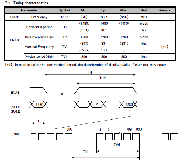
Using the information on the datasheet, you must fill in the display-timings property of your display node in the device tree. This example uses the values on the typical column:
- clock-frequency is the pixel clock in Hz. On the table, this is the Clock Rate so the value is 83500000.
- hactive is the horizontal display resolution in pixels. On the table, this is the Horizontal period (High) THd (1280).
- vactive is the vertical display resolution in pixels. On the table, this is the Vertical period (High) TVd (800).
- hfront-porch is the horizontal front porch, the number of clock pulses (pixels) between the last valid pixel data in the line and the next HSYNC pulse. The datasheet does not provide this number but it provides the complete Horizontal period (TH) and the Horizontal period (High) (THd) so you can calculate the horizontal front porch as TH - THd = 1680 - 1280 = 4001.
- hback-porch is the horizontal back porch, the number of pulses (pixels) between the HSYNC signal and the first valid pixel data. According to the datasheet timings diagram, this value is zero.
- hsync-len is the number of clock pulses (pixels) during which the HSYNC signal is active. There is no entry on the datasheet so you can assume zero1.
- vback-porch is the vertical back porch, the number of lines (HSYNC pulses) from a VSYNC signal to the first valid line. According to the datasheet timings diagram, this value is zero.
- vfront-porch is the vertical front porch, the number of lines (HSYNC pulses) between the last valid line of the frame and the next VSYNC pulse. The datasheet does not provide this number but it provides the complete Vertical period (TV) and the Vertical period (High) (TVd) so you can calculate the vertical front porch as TV - TVd = 831 - 800 = 311.
- vsync-len is the number of HSYNC pulses during which a VSYNC signal is active. There is no entry on the datasheet so you can assume zero1.
NOTES:
1 A deeper analysis of the IPU driver at drivers/mxc/ipu3/ipu_disp.c shows that the hsync-len and vsync-len parameters are not allowed to be zero:
drivers/mxc/ipu3/ipu_disp.c
1037 int32_t ipu_init_sync_panel(struct ipu_soc *ipu, int disp, uint32_t pixel_clk,
1038                             uint16_t width, uint16_t height,
1039                             uint32_t pixel_fmt,
1040                             uint16_t h_start_width, uint16_t h_sync_width,
1041                             uint16_t h_end_width, uint16_t v_start_width,
1042                             uint16_t v_sync_width, uint16_t v_end_width,
1043                             uint32_t v_to_h_sync, ipu_di_signal_cfg_t sig)

[...]

1058         if ((v_sync_width == 0) || (h_sync_width == 0))
1059                 return -EINVAL;
The Horizontal period (TH) must be the sum of hback_porch + hactive + hfront_porch + hsync. The value hactive is the horizontal resolution and must not be touched, so subtract 10 from hfront_porch (400 - 10 = 390) and give it to the hsync (10) to avoid it being zero. Similarly, the Vertical period (TV) must be the sum of vback_porch + vactive + vfront_porch + vsync. The vactive value is the vertical resolution and must not be touched, so subtract 10 from vfront_porch (31 - 10 = 21) and give it to the vsync (10) to avoid it being zero.
Define the display timings in your platform's device tree:
ldb@020e0000 {
    lvds-channel@0 {
        native-mode = <&timing0>;
        timing0: lq121k1lg52 {
            clock-frequency = <83500000>;
            hactive = <1280>;
            vactive = <800>;
            hfront-porch = <390>;
            hback-porch = <0>;
            hsync-len = <11>;
            vback-porch = <0>;
            vfront-porch = <21>;
            vsync-len = <10>;
        };
    };
};
Testing the LCD display
If you see Digi's custom logo in the LCD display during kernel boot process, you have successfully added the display.
To verify correct colors, image dimensions, and positioning, run the fbtest application. To add the fbtest application to your root file system, add the following to your project's conf/local.conf:
IMAGE_INSTALL_append = " fbtest"
To run the application, call fbtest from a console. The application shows the test color chart by default to frame buffer 0 (/dev/fb0). To show the test color chart on a different frame buffer, export the variable FRAMEBUFFER:
export FRAMEBUFFER=/dev/fb2
fbtest
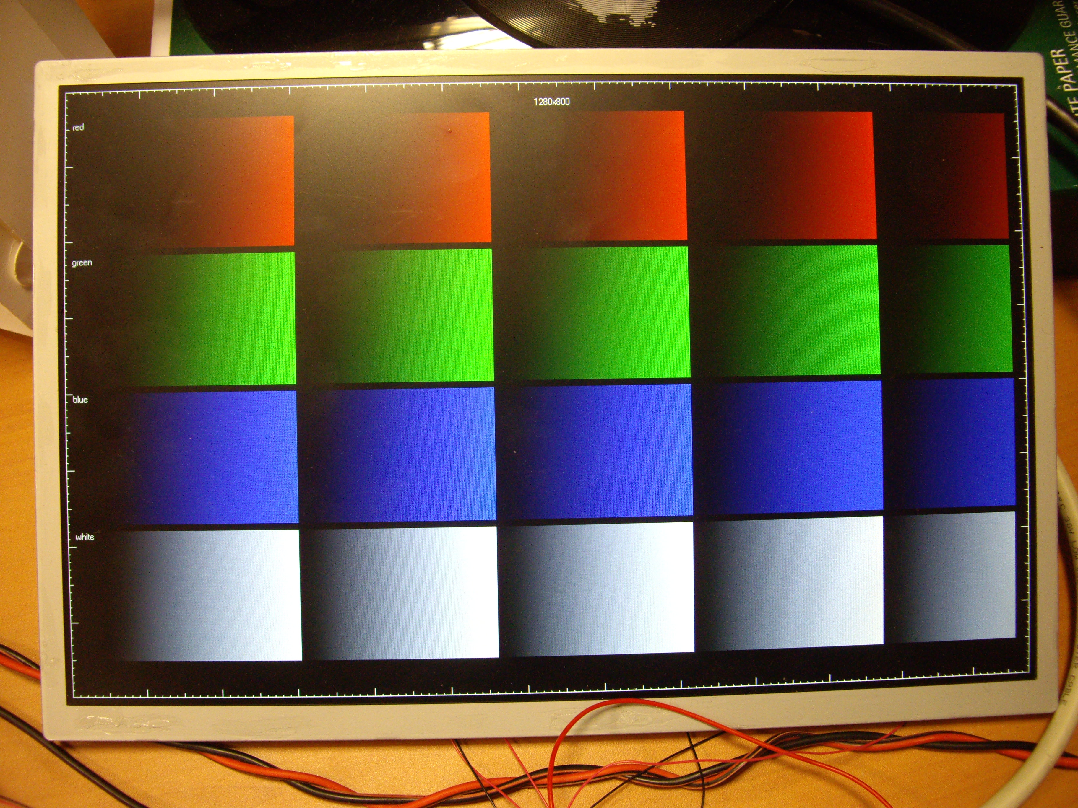
This color chart displays a white one-pixel frame at the edges of the LCD (which allows you to verify correct position and width/height), and gradients of red, green, blue, and white (which allow you to verify correct color depth and format).
If the image is not perfect, try adjusting the display timing values within the margins indicated by the manufacturer on the LCD datasheet.


