Analog input
The analog inputs have the following modes of operation, which are disabled by default. You can enable or disable the modes, but use only one mode for each input.
Voltage input
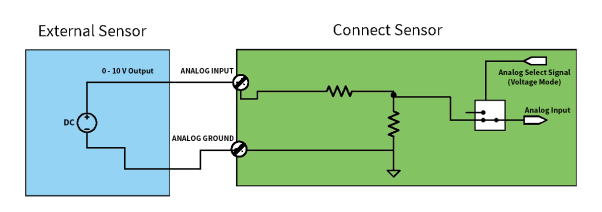
The Connect Sensor+ can monitor a voltage input from 0 V to 10 V. The following schematics show wiring options for 0-10 V input.
Self-powered
This figure shows the schematic when the external sensor is self-powered or powered from a source other than the Connect Sensor+
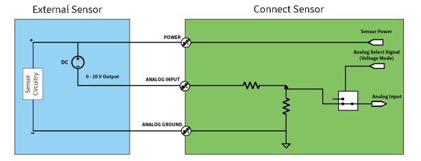
3-wire sensors
This figure shows the schematic when using power from the Connect Sensor+ to power the sensor.
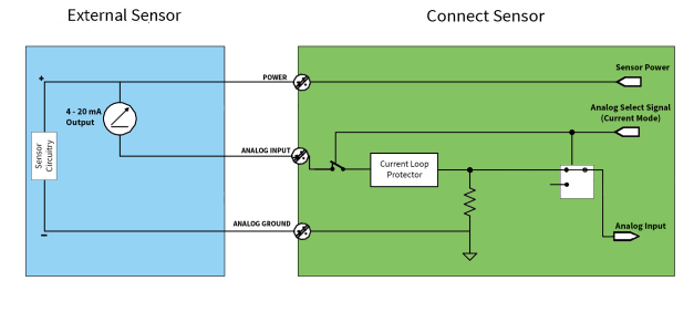
Current loop
The Connect Sensor+ can monitor a current input from 4 mA to 20 mA. The following schematics show wiring options for 4-20 mA inputs.
Self-powered
This figure shows the schematic when the external sensor is self-powered or powered from a source other than the Connect Sensor+.

2-wire (loop-powered) sensors
You can connect the Connect Sensor+ to a 4/20 mA 2-wire sensor, which is also known as a loop-powered sensor.
This figure shows the schematic when using power from the Connect Sensor+ current loop to power a sensor.

Calculating supply voltage for a 2-wire (loop-powered) sensor
The power output from the Connect Sensor+ is configurable. The configured voltage value for the Connect Sensor+ is between the Power and Analog Ground terminals, as shown in the schematic above. The voltage across the terminals of the external sensor device (between Power and Analog Input) fluctuates, depending on the loop current. The fluctuation occurs because the variable loop current through the resistance inside the Connect Sensor+ changes the voltage between the Analog Input and Ground terminals. This is expected behavior for a 4/20 mA 2-wire interface.
When determining the value for the output power, you must calculate the range of voltages to determine whether the voltage setting is sufficient. The voltage across the external sensor device terminals (Power and Analog Input) is always less than the configured voltage.
For example, calculate an estimate of the range of voltage across the external sensor device terminals (Power to Analog Input) when the Analog Output voltage is set to 24 V. The nominal internal resistance of theConnect Sensor+ is 375 ohms, but may vary across current flow and temperature.
- Max: 24 V – (4 mA *375 ohms) ≈ 22.5 V
- Min: 24 V - (20 mA *375 ohms) ≈ 16.5 V
3-wire sensors
This figure shows the schematic when the analog power output from the Connect Sensor+ is powering the sensor.
 PDF
PDF


