In-Premise Display/Meter Simulation Sample
This sample simulates the basic functionality of a Smart Energy In-Premise Display or Meter with an XBee attached to a personal computer such as an XStick, XBee USB adapter, or other serially-attached XBee. It can be used to demonstrate Smart Energy functionality when real SE IPDs and meters are not convenient or available. If you do not already have one of these devices they may be purchased from the Digi website.
Important
XBee modules are not Smart Energy certified for standalone use. In order to join the XBee module to the gateway a test certificate will need to be installed on both the XBee module and the gateway. See Smart Energy Certificate Management for more details on installing test certificates. In particular, obtain a test certificate for both the gateway and the XBee module and install the gateway’s test certificate prior to executing the following procedure.
Getting Started
Download and install USB Serial Driver if not already installed.
Connect the serially-attached XBee to your personal computer.
Upgrade the serially-attached XBee to use Smart Energy router firmware if it is not already. Full instructions and firmware can be found in the ZB to SE conversion kit.
Download and install the In-Premise Display/Meter Simulator if not already installed.
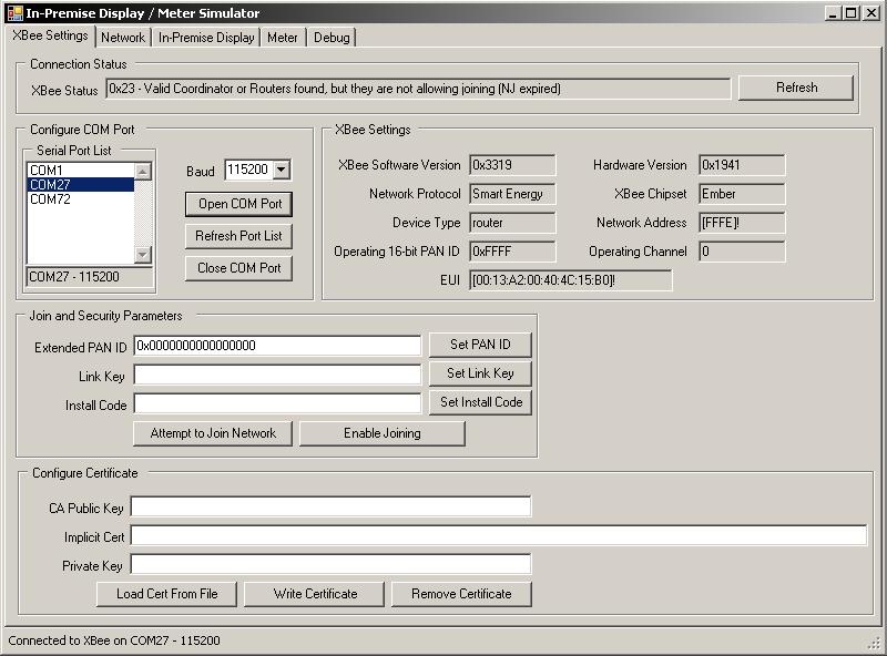
Start In-Premise Display/Meter Simulator.
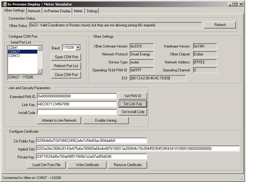
Select the COM port and baud rate of your serially-attached XBee and click Open COM Port. The Baud rate is shown below as 115200 but will commonly need to be set to 9600 after following instructions in the ZB to SE Conversion Kit.
Load the test certificate information that corresponds to the serially-attached XBee. This can be accomplished in two ways:
Load Cert From File
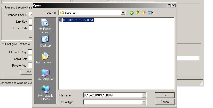
Click Load Cert From File.
Select the test certificate file that corresponds to the EUI field under XBee Settings and click Open.
Manual Entry
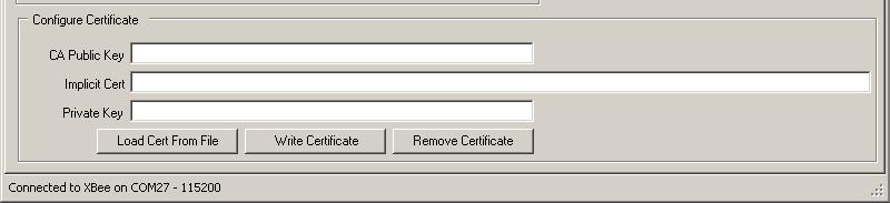
Manually enter the CA Public Key, Implicit Cert and Private Key.

Write the Certificate to the serially-attached XBee by clicking Write Certificate.
Enter a 128-bit hex value of your choosing into the Link Key field and click Set Link Key to write the link key to the serially-attached XBee. Alternately, you may enter Install Code, a 48-, 64-, 96-, or 128-bit hex value (including 16-bit CRC), and click Set Install Code to write a link key computed from the install code to the serially-attached XBee.
Enable joining on the trust center and register the link key / installation code of the XBee. If using an ESI coordinator, send an add_device RPC request to the gateway in order to allow the serially-attached XBee to join the gateway’s network. Set the parameters of the request to correspond to the serially-attached XBee and to enable joining.
Note
The required add_device request is slightly different depending on whether you used a link key or installation code in the previous step. Refer to one of the following templates as appropriate.
For install code:
<add_device synchronous="true">
        <device_address type="MAC">11:22:33:44:55:66:77:88</device_address>
        <join_time>600</join_time>
        <installation_code type="string">1234-5678-90AB-BA9E</installation_code>
</add_device>
For link key:
<add_device synchronous="true">
        <device_address type="MAC">11:22:33:44:55:66:77:88</device_address>
        <join_time>600</join_time>
        <link_key type="int">0x56777777777777777777777777777777</link_key>
</add_device>
Click Attempt to Join Network and wait until XBee Status indicates that the XBee has joined with the network. The XBee Status field will display status indicators as it attempts to join. In case of failure these indicators may aid in troubleshooting.

Network View
The Network tab provides a convenient overview of all endpoints and clusters of devices which have been detected on the network. The information displayed should closely match the information returned by a get_device_information RPC request sent to the gateway.
To detect new devices, endpoints and clusters click Partial Refresh. To clear and rediscover all known device information, click Full Refresh.
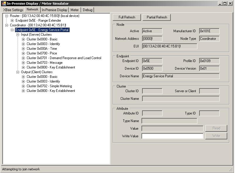
ZCL attributes can be read and written from the Network Tab after selecting an attribute.

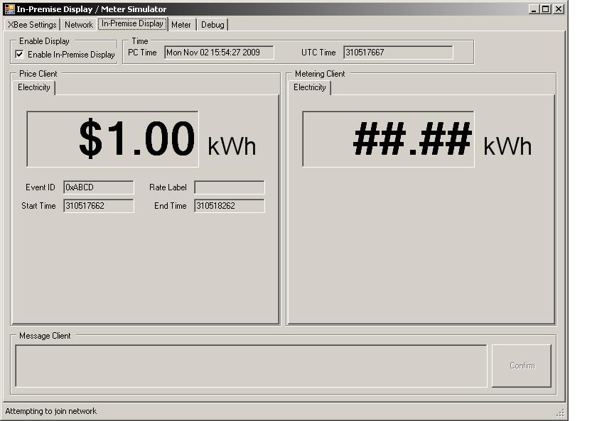
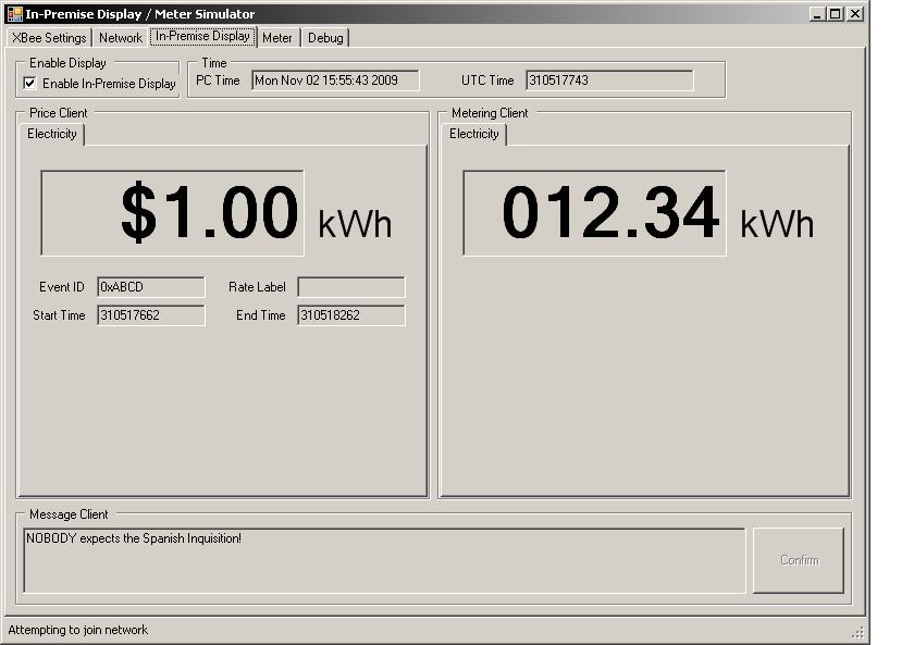
In-Premise Display
To create an In-Premise Display endpoint, go to the In-Premise Display tab and click the Enable In-Premise Display check box. This will create Price, Messaging and Simple Metering client clusters on a new endpoint on the simulated device.
The sample will display the price from any price servers on the network. If there is an ESI gateway on the network, send it a create_price_event RPC request to set the current price. Here is an example:
<create_price_event>
        <record type="PublishPriceRecord">
                <provider_id>1234</provider_id>
                <issuer_event_id>0xABCD</issuer_event_id>
                <duration_in_minutes>10</duration_in_minutes>
                <price>100</price>
        </record>
</create_price_event>
The price event will automatically be sent to all known Price client clusters. You should see the new price value appear. If there is an IPD Router gateway on the network, it should receive the price event and return a received_publish_price* response and an updated_active_price*, assuming there was not another price event with a matching issuer_event_id.
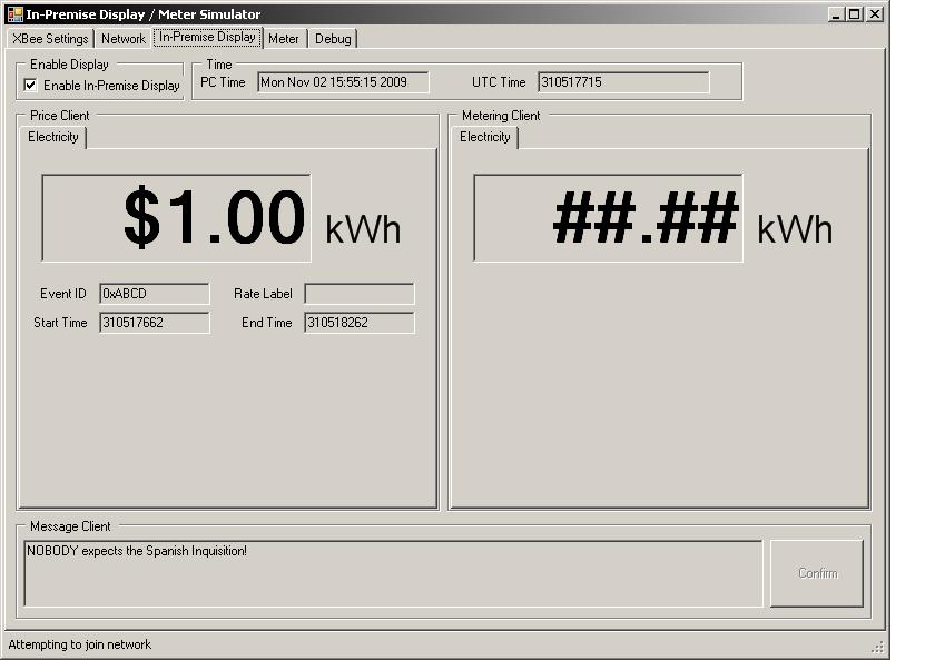
The sample will also display any active messages on the network. If there is an ESI gateway on the network, send it a create_message_event RPC request to display a message. Here is an example:
<create_message_event>
  <record type="DisplayMessageRecord">
    <message_id>0x1234</message_id>
    <start_time>0</start_time>
    <duration_in_minutes>10</duration_in_minutes>
    <message type="string">NOBODY expects the Spanish Inquisition!</message>
  </record>
</create_message_event>
The message event will automatically be sent to all known Messaging client clusters. You should see the new message appear. If there is an IPD Router gateway on the network, it should receive the message event and return a received_display_message* response and an updated_active_message*, assuming there was not another message event with a matching message_id.
Additionally, if a Simple Metering server cluster is found on the network, the current usage information will be automatically retrieved and displayed via ZCL reporting.
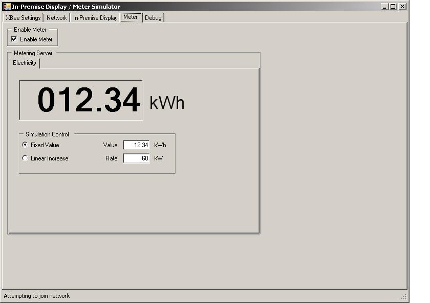
Meter
To create a Metering Device endpoint, go to the Meter tab and click the Enable Meter check box. This will create a Simple Metering server cluster on a new endpoint on the simulated device.
You may set the meter to either have a fixed usage value or a linearly increasing value.