

Some ConnectCore platforms share the same form factor and pad mapping for most interfaces, allowing you to design common hardware compatible with different ConnectCore SOMs. Although the SOMs are not 100% drop-in compatible, a lot of primary functionality is pin-to-pin compatible between platforms. This is called a compatible pinout in the Digi Smart IOmux application. A compatible pinout is a set of definitions containing the pad mapping and MUX interface configuration for compatible ConnectCore platforms. Currently, there is one compatible pinout defined in the Smart IOmux application: the Digi SMT Plus 40x45, which specifies the ConnectCore 8X and ConnectCore 8M Nano as compatible platforms.
The Smart IOmux designs that are compatible with multiple ConnectCore platforms are called cross-platform designs. The application enables you to create cross-platform designs without worrying about the MUX configuration that should be assigned to each pad to keep that compatibility. Choose the interfaces you want in your design, and Digi Smart IOmux automatically chooses the corresponding MUX to keep compatibility.
When creating cross-platform designs, Smart IOmux limits the number of interfaces and settings you can configure in the design to make sure it keeps compatibility between all the platforms defined in the pinout.
|
You can switch the base platform of a cross-platform design at any time to select any of the platforms defined in the compatible pinout being used. You can also remove the cross-platform compatibility of a design and continue working with it as a standard design at any time. |
To create a cross-platform design in Smart IOmux:
-
Click the New icon from the main toolbar. The Create a new design wizard appears. (You can also go to File > New design or use the shortcut Ctrl+N.)
-
Fill in the name and location page fields:
-
Design name: The name of your design.
-
Design location: The destination file to save your design.
-
-
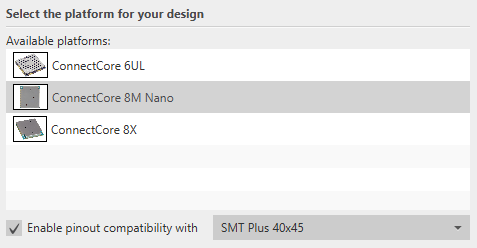
Click Next. The Select the platform page appears.
-
Select your base platform.
Although you are creating a cross-platform design, you need to base the design on one platform as the MUX configuration of the components change between platforms. If the platform you have selected is included in any compatible pinout, the Enable pinout compatibility with option is enabled. At the moment, the platforms that have a compatible layout associated are:
-
ConnectCore 8M Nano.
-
ConnectCore 8X.
-
-
Check the Enable pinout compatibility with option and select the compatible pinout you want to use. Remember that when doing this you are creating a design that shares compatibility with all the platforms defined in that layout.
-
Select the platform variant of the design and click Next. The Configure the design page appears.
-
Choose the platform layout you want to use for your design:
-
LGA pads layout: Use the pads that populate the back of the module.
-
Castellated pads layout: Use the pads along the sides of the module.
The number and functionality of castellated pins are limited. If you select the castellated pads layout, some components will not be available in your design.
-
-
Select the initial design setup:
-
Create an empty design to start from scratch.
-
Start from an existing template to use one of the templates provided by Digi.
-
-
If you choose to start from an existing template, select one from the list to begin a design based on that template.
-
Click Finish. The wizard dialog closes and your design opens in the application.
