

The ConnectCore 8X and the ConnectCore 8M system-on-modules share a common SMTPlus 45x40 form factor. This means that several interfaces are pin-to-pin compatible, enabling you to make a single mother board work for both the ConnectCore 8X and ConnectCore 8M series of Digi products. Choosing a product with a common form factor enables you to choose a path toward optimized costs, maximum design longevity, and future compatibility without compromising your ability to optimize the board design. You can also leverage common code bases, documentation, and in-house knowledge as your product scales through the product family.
This document serves as a guide for creating a design compatible across SOMs that share the common SMTPlus 45x40 footprint. It provides proven methodology and best practices for creating a compatible design without incurring additional carrier board modifications.
|
The Digi ConnectCore Smart IOmux tool can help with the complex task of matching required functionality with multiplexed SOM/CPU pads. You can enter the list of interfaces required by your project and then use the Smart IOmux graphical interface to mock up configuration options, resulting in full pin assignment and device tree snippets that match your desired functionality. See Digi ConnectCore Smart IOmux for more detailed instructions on using the tool to explore configuration options and resolve conflicts. |
ConnectCore 8X and 8M feature comparison
The following table summarizes the functionality available on the ConnectCore 8X and ConnectCore 8M platforms:
| Functionality | ConnectCore 8X | ConnectCore 8M Nano | ConnectCore 8M Mini |
|---|---|---|---|
CPU |
|
|
|
MCA |
Arm Cortex-M0+ Digi Microcontroller Assist™ (MCA) subsystem |
||
DDR |
Up to 2 GB, 32-bit 1.2 GHz LPDDR4 memory |
Up to 1 GB, 16-bit 1.5 GHz LPDDR4 memory |
Up to 2 GB, 32-bit LPDDR4 memory |
Flash memory |
Up to 16 GB, 8-bit eMMC memory |
Up to 8 GB, 8-bit eMMC memory |
Up to 8 GB, 8-bit eMMC memory |
PMIC |
NXP PF8100 Power Management IC (PMIC) |
NXP PCA6450A power management IC (PMIC) |
|
Crypto chip |
CryptoAuthentication device |
||
Wi-Fi |
2x2 MIMO IEEE802.11 a/b/g/n/ac |
1x1 SISO IEEE802.11 a/b/g/n/ac |
|
Bluetooth |
Bluetooth 5.0 |
||
Debug |
System JTAG controller |
||
Single Wired Debug (SWD) interface for the MCA |
|||
CPU Interfaces |
x146 General purpose IOs |
x110 General purpose IOs |
x131 General purpose IOs |
x1 USBOTG 2.0 (with PHY) |
x2 USBOTG 2.0 (with PHY) |
||
x1 USBOTG 3.0 with PHY - USB 3.0 can be used as USB 2.0 |
|||
x2 Gigabit Ethernet controller |
x1 Gigabit Ethernet controller |
||
x6 UARTs:
|
x4 UARTs
|
||
x10 I2C:
|
x4 I2C |
||
x4 SPI |
x3 SPI |
||
x2 Quad SPI or 1x Octal SPI (FlexSPI) |
x1 Quad SPI |
||
x4 SAI:
|
x5 SAI:
|
x5 SAI:
|
|
x1 SD 3.0 card interface |
x3 Ultra Secure Digital Host Controller (uSDHC) interfaces |
||
x2 MIPI-DSI/LDVS |
x1 MIPI-DSI |
||
x1 MIPI-CSI |
|||
x4 PWM channels |
|||
PCIe 3.0 (not available in wireless variants) |
PCIe 3.0 |
||
x3 CAN/CAN-FD |
|||
Media Local Bus (MLB25/50) |
|||
x1 24-bit parallel display |
|||
x1 8-bit parallel CSI |
|||
x1 Enhanced Serial Audio Interface (ESAI) |
|||
x2 ASRC (Asynchronous Sample Rate Converter) |
|||
x1 SPDIF |
|||
MPEG-2 Transport Stream |
|||
x1 12-bit, 6 channel ADC converter |
|||
x1 4x4 KPP (Key Pad Port) |
|||
x1 MQS (Medium Quality Sound) |
|||
Compatibility within ConnectCore 8M series (Nano and Mini)
Connectivity differences by interface
The functionality on the ConnectCore 8M Nano and the ConnectCore 8M Mini sometimes differs by pad. The following table details interface availability by platform.
 = available
 = not available
| Port | ConnectCore 8M Mini | ConnectCore 8M Nano | Comments |
|---|---|---|---|
PCIe |
|
|
Pads G3, G4, G6, G7, G9 and G10 unconnected on the CC8M Nano. |
USB2 |
|
|
Pads E7, A9, A8 and C10 unconnected on the CC8M Nano. |
SAI1 |
|
|
Pads B19, B20, B21, C20, B22, AH22, AH23, AK28, AJ22, AJ24, AH20, AJ21, AK26, AK27, AH25, AH26, AJ25, AH24, AJ23, R29 and P29 unconnected on the CC8M Nano. |
SAI7 |
|
|
See the Hardware reference manuals for a complete list of functionality available by platform.
IOMUX differences
The i.MX8M Nano supports a limited subset of the peripherals available on the i.MX8M Mini. Since the i.MX8M Nano supports fewer interfaces, its signals can be multiplexed to more pads.
You can find full pinout tables in the ConnectCore 8M Nano and ConnectCore 8M Mini Hardware Reference Manuals.
The following table lists the IOMUX differences on the ConnectCore 8M Nano.
-
Red text denotes functionality removed from the ConnectCore 8M Nano, meaning it is only available on the ConnectCore 8M Mini.
-
Normal text indicates functionality that is available only on the ConnectCore 8M Nano.
-
Empty cells indicate no difference in functionality between the ConnectCore 8M Nano and ConnectCore 8M Mini for that pad.
ConnectCore 8M Nano IOMUX options
| Pad | 0 | ALT1 | ALT2 | ALT3 | ALT4 | 5 | ALT6 |
|---|---|---|---|---|---|---|---|
AJ28 |
I2C1_SCL |
||||||
AJ27 |
I2C1_SDA |
||||||
AG11 |
PWM1_OUT |
||||||
AG12 |
PWM2_OUT |
||||||
AG13 |
PWM3_OUT |
||||||
AG10 |
PWM2_OUT |
||||||
C7 |
USB_OTG_PWR |
||||||
C11 |
USB2_OTG_OC |
||||||
A10 |
SAI6_TX_DATA[0] |
PDM_BIT[3] |
SPDIF_OUT |
USDHC3_STROBE |
|||
A11 |
SAI6_TX_SYNC |
PDM_BIT[2] |
SPDIF_IN |
USDHC3_DATA5 |
|||
A19 |
SAI6_TX_BCLK |
PDM_BIT[1] |
SPDIF_EXT_CLK |
USDHC3_DATA6 |
|||
A20 |
SAI6_RX_DATA[0] |
PDM_BIT[3] |
USDHC3_DATA7 |
||||
A21 |
SAI6_RX_SYNC |
PDM_BIT[2] |
USDHC3_CD_B |
||||
A22 |
SAI6_RX_BCLK |
PDM_BIT[1] |
USDHC3_WP |
||||
A23 |
SAI6_MCLK |
USDHC3_DATA0 |
|||||
A24 |
SAI7_TX_DATA[0] |
USDHC3_DATA1 |
|||||
A17 |
SAI7_TX_SYNC |
PDM_BIT[3] |
USDHC3_DATA2 |
||||
A18 |
SAI7_TX_BCLK |
PDM_BIT[2] |
USDHC3_DATA3 |
||||
A16 |
SAI7_RX_DATA[0] |
PDM_BIT[1] |
USDHC3_DATA4 |
||||
A15 |
SAI7_RX_SYNC |
PDM_BIT[0] |
USDHC3_RESET_B |
||||
A14 |
SAI7_RX_BCLK |
PDM_CLK |
USDHC3_CLK |
||||
A13 |
SAI7_MCLK |
SPDIF_IN |
USDHC3_CMD |
||||
D12 |
ENET_MDC |
UART1_TX |
|||||
D11 |
ENET_MDIO |
UART1_RX |
|||||
D9 |
ENET_RGMII_TD1 |
UART1_RTS_B |
|||||
D8 |
ENET_RGMII_TD0 |
UART1_CTS_B |
|||||
D6 |
ENET_RGMII_RD0 |
UART2_TX |
|||||
D5 |
ENET_RGMII_RD1 |
UART2_RX |
|||||
D14 |
ENET_RGMII_TX_CTL |
I2C1_SCL |
UART2_RTS_B |
||||
D13 |
ENET_TX_ER |
I2C1_SDA |
UART2_CTS_B |
||||
D10 |
ENET_RGMII_RX_CTL |
I2C2_SCL |
UART3_TX |
||||
D7 |
ENET_RX_ER |
I2C2_SDA |
UART3_RX |
||||
G18 |
I2C3_SDA |
UART3_CTS_B |
|||||
L1 |
SAI5_RX_SYNC |
ECSPI2_SCLK |
UART4_RX |
SAI5_MCLK |
|||
F1 |
SAI5_RX_BCLK |
ECSPI2_MOSI |
UART4_TX |
PDM_CLK |
|||
G1 |
SAI5_RX_DATA[0] |
I2C4_SDA |
UART2_RX |
PDM_BIT[0] |
|||
H1 |
SAI5_TX_SYNC |
I2C4_SCL |
UART2_TX |
PDM_BIT[1] |
|||
J1 |
SAI5_TX_BCLK |
ECSPI2_SS0 |
SPDIF_OUT |
PDM_BIT[2] |
|||
K1 |
SAI5_TX_DATA[0] |
ECSPI2_MISO |
SPDIF_IN |
PDM_BIT[3] |
|||
F3 |
CORESIGHT_EVENTI |
||||||
AG28 |
PDM_BIT[0] |
UART3_RX |
CORESIGHT_TRACE_CLK |
||||
K29 |
PDM_BIT[1] |
UART3_TX |
CORESIGHT_TRACE_CTL |
||||
AL18 |
PDM_BIT[2] |
UART4_RX |
CORESIGHT_TRACE[4] |
||||
A12 |
PDM_BIT[3] |
UART4_TX |
CORESIGHT_TRACE[5] |
||||
AG15 |
I2C4_SDA |
CORESIGHT_TRACE[6] |
|||||
D25 |
CORESIGHT_TRACE[7] |
||||||
AG25 |
PDM_CLK |
I2C3_SCL |
CORESIGHT_TRACE[12] |
||||
E25 |
SAI1_TX_DATA[0] |
||||||
E24 |
SAI1_TX_DATA[1] |
||||||
D19 |
SAI1_TX_DATA[2] |
||||||
AG8 |
SAI1_TX_DATA[3] |
SAI1_TX_SYNC |
|||||
E3 |
SAI1_TX_DATA[4] |
SAI1_TX_SYNC |
|||||
E27 |
SAI1_TX_DATA[5] |
SAI1_TX_SYNC |
|||||
C24 |
SAI1_TX_BCLK |
||||||
W29 |
PDM_BIT[2] |
||||||
V29 |
PDM_BIT[1] |
||||||
E21 |
SAI2_TX_DATA[1] |
PDM_BIT[3] |
|||||
C19 |
PDM_BIT[2] |
||||||
E23 |
PDM_BIT[1] |
||||||
B24 |
SAI3_MCLK |
||||||
E28 |
SPDIF_IN |
PDM_BIT[0] |
|||||
F12 |
SAI2_RX_DATA[1] |
PDM_CLK |
|||||
F11 |
SAI3_TX_DATA1 |
PDM_BIT[1] |
|||||
E12 |
PDM_BIT[3] |
||||||
E13 |
SAI2_TX_DATA[1] |
PDM_BIT[2] |
|||||
F29 |
SPDIF_EXT_CLK |
||||||
G29 |
SPDIF_OUT |
SPDIF_IN |
|||||
R1 |
I2C1_SCL |
SAI5_RX_SYNC |
|||||
P1 |
I2C1_SDA |
SAI5_RX_BCLK |
|||||
M29 |
I2C2_SCL |
SAI5_RX_DATA[0] |
|||||
N29 |
I2C2_SDA |
SAI5_RX_DATA[1] |
SAI5_TX_SYNC |
||||
D17 |
I2C3_SCL |
SAI5_RX_DATA[2] |
SAI5_TX_BCLK |
||||
E18 |
I2C3_SDA |
SAI5_RX_DATA[3] |
SAI5_TX_DATA[0] |
||||
E22 |
I2C4_SCL |
SAI5_MCLK |
|||||
E19 |
I2C4_SDA |
||||||
F28 |
ECSPI1_MISO |
||||||
E29 |
ECSPI1_SS0 |
||||||
AK25 |
ECSPI2_SCLK |
||||||
AK24 |
ECSPI2_MOSI |
||||||
V1 |
PCIE_CLKREQ_Q |
ECSPI2_MISO |
|||||
W1 |
ECSPI2_SS0 |
||||||
C18 |
GPT1_COMPARE3 |
||||||
C17 |
GPT1_COMPARE2 |
||||||
AG26 |
GPT1_CAPTURE1 |
||||||
AG27 |
GPT1_CLK |
||||||
U29 |
PCIE_CLKREQ_B |
GPT1_COMPARE1 |
|||||
T29 |
GPT1_CAPTURE1 |
Power architecture
The following diagram shows the common high-level power architecture for the ConnectCore 8X/8M System-on-Module:
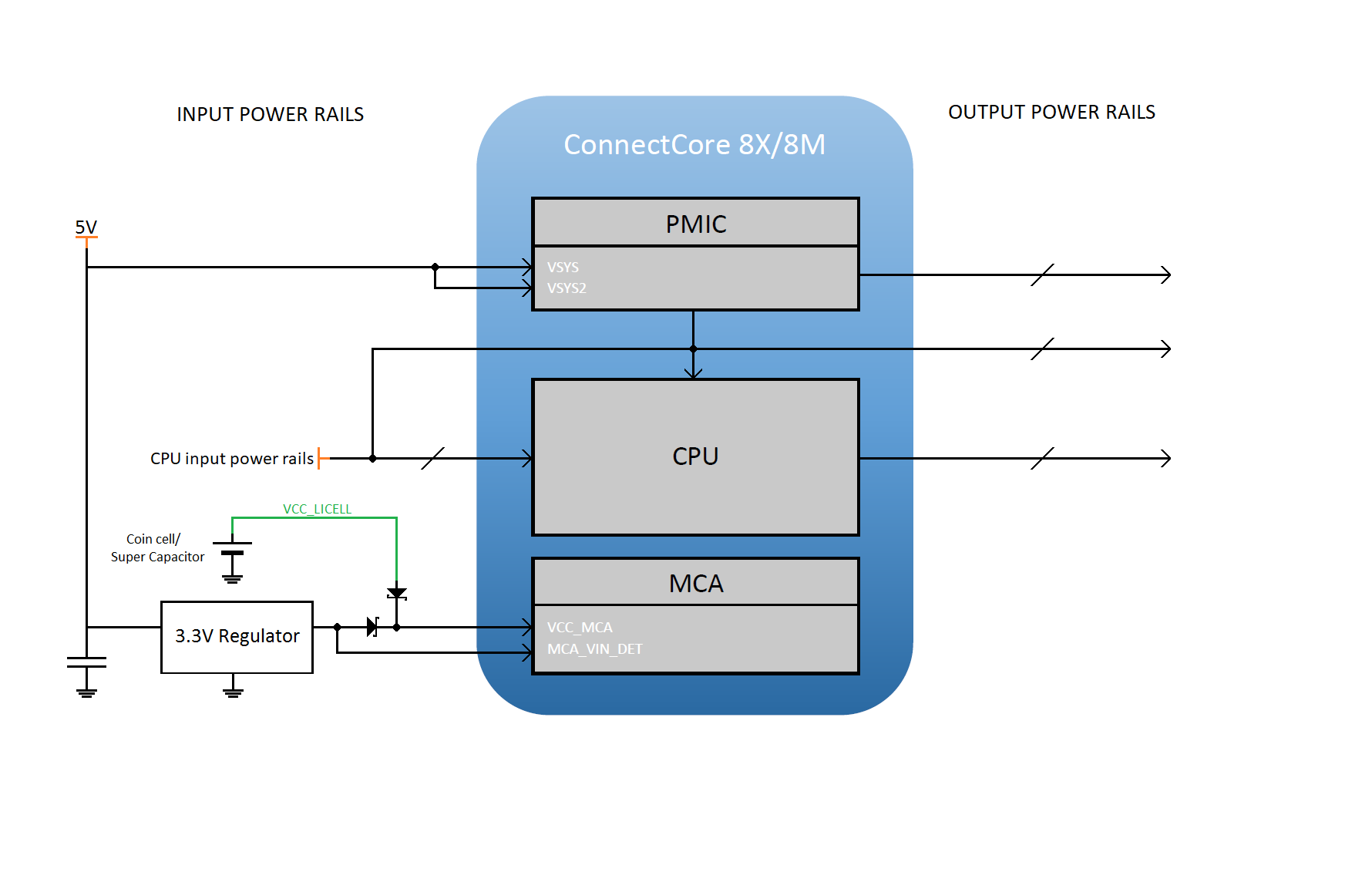
Although the input and output power rails of both SOMs are similar, the internal power architecture is different and the electrical characteristics for each particular rail may also differ. The following sections contain a more detailed explanation of power architecture differences between the ConnectCore 8X and ConnectCore 8M platforms.
Input power rails
Both platforms have two main input voltages:
-
5 V power supply: This input voltage powers the internal PMIC, which generates most of the internal voltages required by the electronics included in the SOM. These voltages can also be used on the carrier board to power the peripherals.
-
3.3 V power supply: This power supply powers the internal Microcontroller Assist (MCA), which assists the i.MX 8X/8M processor with advanced operations related to power management, security, and system reliability.
In addition, some of the CPU input voltages (which power different CPU peripherals such as Ethernet) are tied to the module pads. This allows you to select the voltage level at the carrier board based on the characteristics of the connected peripheral. The PMIC output power rails are available on the module pads for this purpose.
The following table summarizes the input power rails of both the ConnectCore 8X and the ConnectCore 8M platforms:
| Device powered | ConnectCore 8X | ConnectCore 8M | ||
|---|---|---|---|---|
Power rail |
Operating voltage |
Power rail |
Operating voltage |
|
PMIC |
VSYS |
5 V |
VSYS |
5 V |
VSYS2 |
5 V |
VSYS2 |
5V |
|
LDO3IN |
2.5-5.5 V |
|||
LDO4IN |
2.5-5.5 V |
|||
CPU |
VDD_USDHC1 |
1.8 V/3.3 V |
VDD_USDHC2 |
1.8 V/3.3 V |
VDD_ENET0 |
1.8 V/3.3 V |
VDD_ENET |
1.8 V/2.5 V/3.3 V |
|
VDD_SPI_SAI |
1.8 V/3.3 V |
VDD_UART |
1.8 V/3.3 V |
|
VDD_CSI |
1.8 V/3.3 V |
|||
VDD_ESAI_SPDIF |
1.8 V/2.5 V/3.3 V |
|||
VDD_QSPI0B |
1.8 V/3.3 V |
|||
VDD_MIPI_DSI_DIG |
1.8 V/3.3 V |
|||
USB_OTG1_VBUS |
5 V |
|||
MCA |
VCC_MCA |
3.0 V |
VCC_MCA |
3.0 V |
Output power rails
Each platform has specific PMIC regulators that are intended to power external circuitry.
| In some cases, these regulators are also used internally in the SOM, so do not exceed the power capabilities of these regulators. |
The following tables summarize the output power rails of both the ConnectCore 8X and the ConnectCore 8M platforms:
| ConnectCore 8X | ConnectCore 8M | ||||||
|---|---|---|---|---|---|---|---|
Power rail |
Operating voltage |
Used internally in the SOM |
Output current[1] |
Power rail |
Operating voltage |
Used internally in the SOM |
Output current[1] |
3V3 |
3.3 V |
YES |
2500 mA |
3V3 |
3.3 V |
YES |
3000 mA |
1V8 |
1.8 V |
YES |
2500 mA |
1V8 |
1.8 V |
YES |
2000 mA |
LDO3 |
1.5 V-5 V |
NO |
400 mA |
VDDA_1V8 |
1.8 V |
YES |
300 mA |
LDO4 |
1.5 V-5 V |
NO |
400 mA |
MUX_3V3_1V8 |
1.8 V/3.3 V |
NO |
150 mA |
VDD_EMMC0 |
3.3 V |
YES |
400 mA |
||||
VCC_SCU_1V8 |
1.8 V |
YES |
400 mA |
||||
VCC_LICELL |
1.8-3.6 V |
YES |
0.06 mA |
||||
1. Some output power rails are also used inside the SOM, so the total power available for powering external circuitry will be lower than the value specified in the table.
| Power architecture differs by module. This means that the electrical operating conditions for some specific interface may be different in each platform. See Pinout compatibility for specific voltage levels. |
See the Hardware reference manuals for a complete description of power architecture.
MCA
Both platforms integrate the Microcontroller Assist (MCA) hardware. However, this device has a different package in each design, so the ConnectCore 8X module has the following four additional IOs than the ConnectCore 8M:
-
MCA_IO5
-
MCA_IO6
-
MCA_IO7
-
MCA_IO8
Cryptochip
The ConnectCore 8X and ConnectCore 8M platforms include a cryptoauthentication device, which is a highly secure cryptographic co-processor with secure hardware-based key storage. The implementation of this device is exactly the same in both platforms.
Wireless
The ConnectCore 8X and ConnectCore 8M SOMs have the same wireless capabilities at a functional level. Both support Bluetooth and Wi-Fi, although performance will differ due to differences in the hardware design itself. The ConnectCore 8X uses a QCA6574AU MAC, supporting dual antenna (MIMO). The ConnectCore 8M uses a QCA6564A MAC, supporting single antenna (SISO).
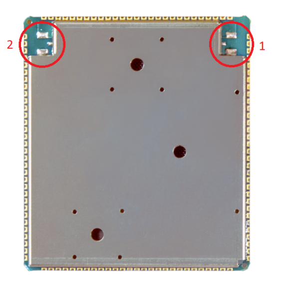
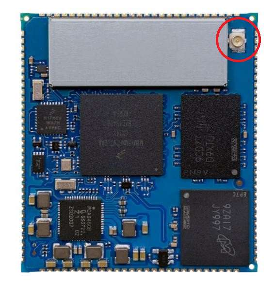
The primary antenna on the ConnectCore 8X SOM is located in the same position as the antenna of the ConnectCore 8M platform:
| ConnectCore 8X antenna location | ConnectCore 8M antenna location |
|---|---|
|
|
Pinout compatibility
The common SMTPlus 45x40 form factor ensures a high level of pin-to-pin compatibility between the ConnectCore 8X and the ConnectCore 8M modules.
| The ConnectCore 8X is a more powerful platform than the ConnectCore 8M, so some features will not be available in the ConnectCore 8M module. |
Most of the CPU pads allow for multiple IOMUX configurations. Compatibility is only guaranteed for the primary functionality defined in the SMTPlus 45x40 form factor.
The naming of the pads in each specific platform may differ due to factors such as a different CPU index of the interface. For example, in those pads where a UART is available, it may be named UART1 in one platform and UART2 in another, but in both cases a UART is secured on those pads.
The following list describes pin-to-pin interfaces that are compatible with both platforms:
-
x1 USDHC
-
x2 SAI:
-
x1 4-wire
-
x1 3-wire (receiver only)
-
-
x2 SPI
-
x1 PWM
-
x19 free GPIOs (most of the compatible interface pads can also be configured as GPIOs)
-
x2 USB OTG (only 1 available in the ConnectCore 8M Nano)
-
x1 Ethernet
-
x1 PCIe (not available in the ConnectCore 8M Nano)
-
x1 MIPI DSI
-
x1 MIPI CSI
-
MCA functionality (through IOMUX configuration, i.e. not everything supported at the same time):
-
x2 4-wire UART
-
x8 ADCs
-
See Form-factor compatible interfaces for a detailed description of the compatibility of each pad and how to solve possible conflicts between platforms.
Guidelines for creating a compatible design
This section describes three different scenarios that may occur when designing a carrier board compatible with both the ConnectCore 8X and ConnectCore 8M SOMs:
-
The desired functionality is available on both platforms in pin-to-pin-compatible pads.
-
The desired functionality is not pin-to-pin compatible, but it is supported on both platforms (through different pads).
-
The functionality is only supported on one platform.
In all these cases, the Digi ConnectCore Smart IOmux tool can help with the complex task of matching required functionality with multiplexed SOM/CPU pads. You can enter the list of interfaces required by your project and then use the Smart IOmux graphical interface to mock up configuration options, resulting in full pin assignment and device tree snippets that match your desired functionality.
See Digi ConnectCore Smart IOmux for more detailed instructions on using the tool to explore configuration options and resolve conflicts.
Pin-to-pin compatible functionality (same pads)
Whenever the required functionality is pin-to-pin compatible in both platforms, you can connect the module pads directly to the desired peripherals. Note that you do need to make sure the operating voltage is the same in both platforms. If the voltages differ, you must add the necessary voltage adapters in the carrier board and populate them depending on the variant of the product being built.
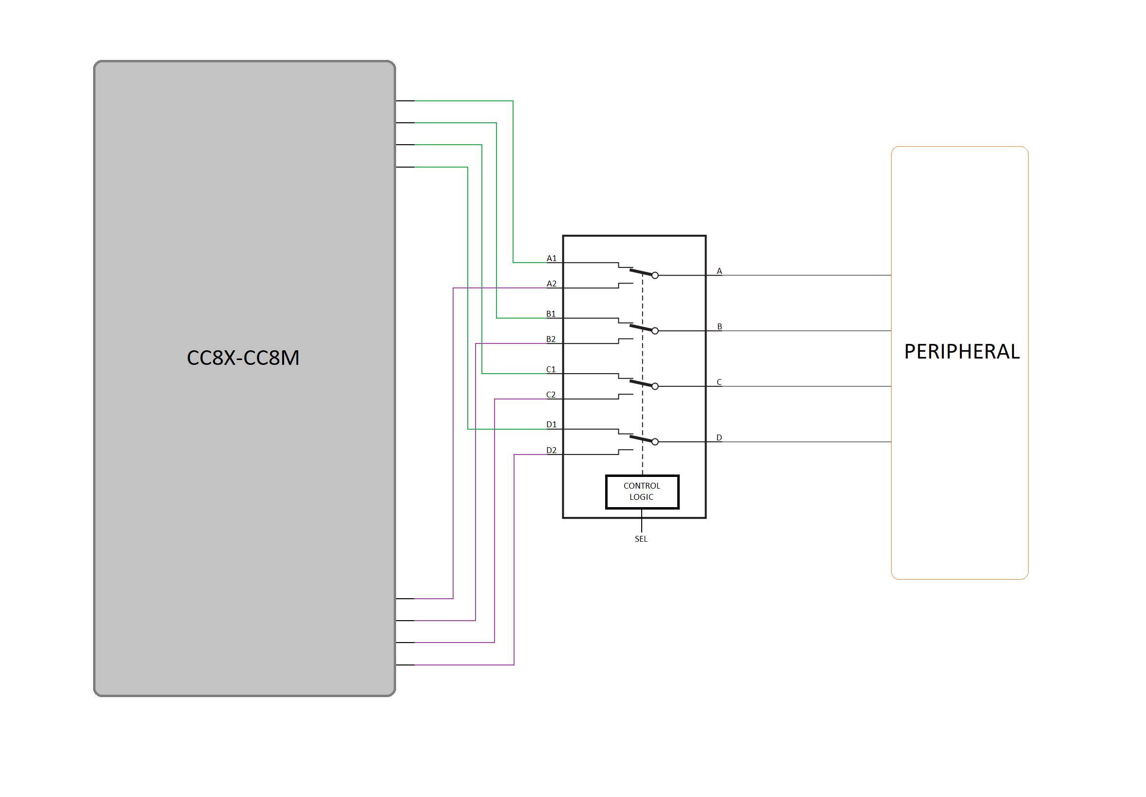
Not pin-to-pin compatible functionality (different pads)
In this scenario, the conflicts can be solved at the carrier board level. Each platform will use different pads to connect to the external peripheral. There are two ways to address this conflict, each one having its own counterpoint:
-
Use 0-ohm resistors to select which module pads are connected to the peripheral. This implies having a different carrier board BOM depending on the SOM populated. In addition, when managing high-speed interfaces, take special care with the layout not to create stabs that may impact the performance.
-
Add a switch connecting the peripheral to one group of pads or the other, depending on the platform used. This solution implies additional components and cost.
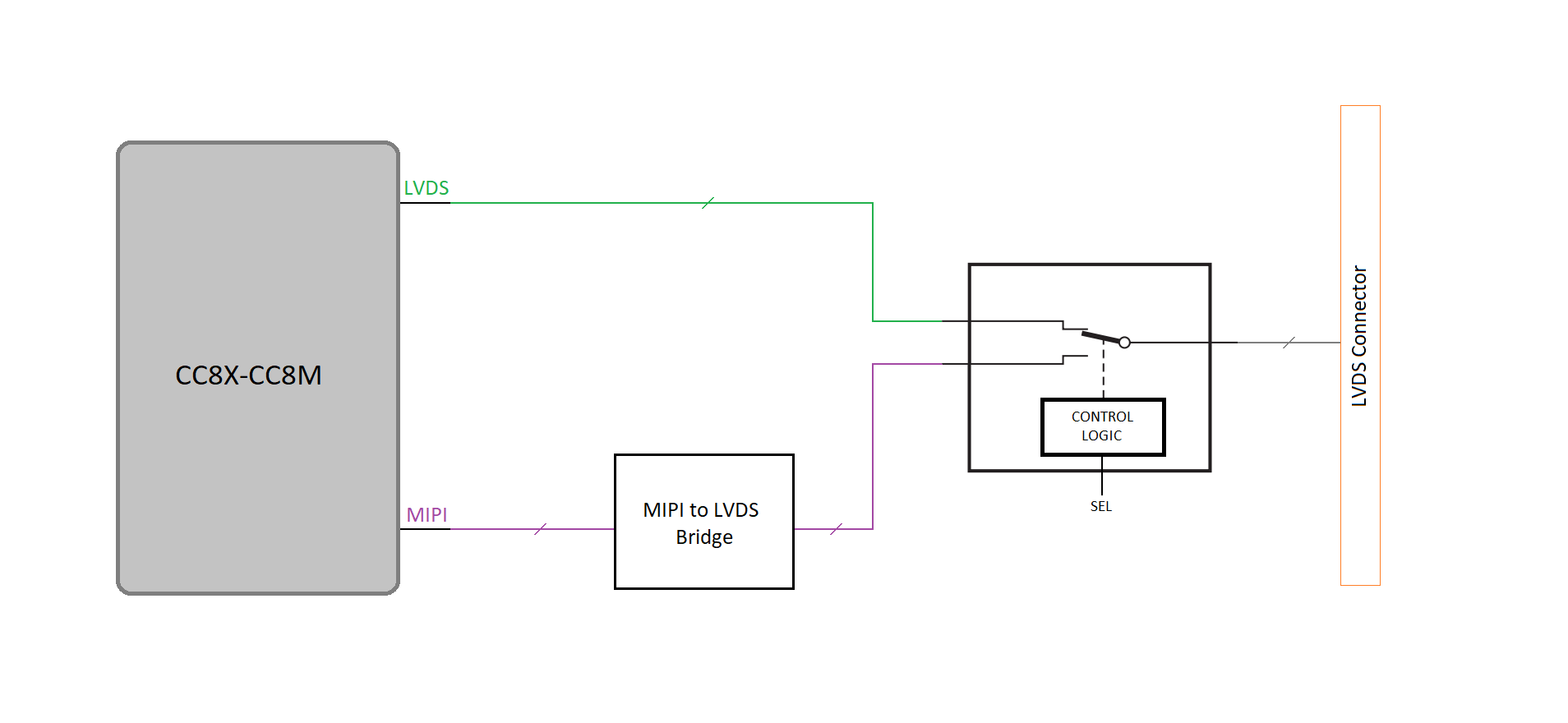
Functionality supported by one platform
In this case, you must use external circuitry to provide the functionality that is not available.
The following example demonstrates an approach to solving the lack of an LVDS interface on the ConnectCore 8M.
Pad configuration
It is important to highlight that module pad configuration may differ between platforms. Some of the electrical parameters of the pads (such as drive strength, pull-up/down configuration, or hysteresis) may have different configuration options on different modules. The Digi ConnectCore Smart IOmux tool helps you configure these pad settings when creating a compatible design between platforms.
Form-factor compatible interfaces
The following tables track the pinout for both platforms, showing default functionality for each pad. Possible conflicts or considerations for specific pads are noted.
Power
| Pad | Functionality | ConnectCore 8X | ConnectCore 8M | Compatible | Comments |
|---|---|---|---|---|---|
AL6 |
VSYS |
VSYS |
VSYS |
|
|
AL7 |
|
||||
AL8 |
|
||||
AJ2 |
VSYS2 |
VSYS2 |
VSYS2 |
|
|
AJ3 |
|
||||
AJ4 |
|
||||
AK2 |
|
||||
AK3 |
|
||||
AK4 |
|
||||
AK1 |
3V3 |
3V3 |
3V3 |
|
|
AL2 |
|
||||
AL3 |
|
||||
AM3 |
|
||||
AM4 |
|
||||
AH1 |
1V8 |
1V8 |
1V8 |
|
|
AH2 |
|
||||
AH3 |
|
||||
AJ8 |
LDOx_IN |
LDO3IN |
NC |
- |
|
AJ10 |
LDOx |
LDO3 |
NC |
- |
|
AH9 |
LDOy_IN |
LDO4IN |
NC |
- |
|
AH7 |
LDOy |
LDO4 |
NC |
- |
|
F20 |
RESERVED |
RESERVED |
MUX_3V3_1V8 |
|
F20 is tied to an internal power domain in the ConnectCore 8X SOM. Do not drive this pad externally. |
AH13 |
VSELECT |
VLDO2_VSELECT |
MUX_VSELECT |
|
This pin selects the operation voltage of a different regulator in each platform. |
AM21 |
VCC_MCA |
VCC_MCA |
VCC_MCA |
|
|
AM8 |
VCC_LICELL |
VCC_LICELL |
NC |
- |
|
AA29 |
Output power rail |
VCC_SCU_1V8 |
1V8 |
||
AJ13 |
VCC_SNVS |
VCC_SNVS_LDO_1V8 |
NC |
- |
|
N1 |
VDD_USDHCx |
VDD_USDHC1 |
VDD_USDHC2 |
|
|
U1 |
Input power rail |
VDD_MIPI_DSI_DIG |
NC |
- |
|
D15 |
VDD_ENET |
VDD_ENET0 |
VDD_ENET0 |
|
|
E14 |
Input power rail |
VDD_ESAI_SPDIF |
NC |
- |
|
E16 |
Input power rail |
VDD_SPI_SAI |
VDD_UART |
- |
|
AG17 |
Input power rail |
VDD_QSPI0B |
NC |
- |
|
AG22 |
Input power rail |
VDD_CSI |
VDD_SAI1 |
- |
|
F2 |
Input power rail |
VDD_PCIE_DIG |
NC |
- |
|
E5 |
Output power rail |
VDD_EMMC0 |
1V8 |
|
[NOTE] This pad is a 1.8 V general purpose output in the ConnectCore 8M, but an internally dedicated 3.3 V supply on the ConnectCore 8X. Digi recommends you leave this pad floating. |
AH18 |
Outptu power rail |
NVCC_MIPI_CSI_DSI |
VDDA_1V8 |
- |
|
AG24 |
VDD_ADC |
VDD_ADC_1V8 |
NC |
- |
|
J29 |
ADC_VREFH |
ADC_VREFH |
NC |
- |
|
F17 |
3V3_RF |
3V3_RF |
3V3_RF |
|
|
F18 |
3V3_RF |
3V3_RF |
3V3_RF |
|
CPU control
| Pad | Functionality | ConnectCore 8X | ConnectCore 8M | Compatible | Comments |
|---|---|---|---|---|---|
AG18 |
IMXx_ON_OFF |
IMX8_ON_OFF |
IMX8_ON_OFF |
|
|
AH10 |
POR_B |
POR_B |
POR_B |
|
|
AJ12 |
PWR_ON |
PWR_ON |
PWR_ON |
|
|
AJ11 |
PMIC_STANDBY |
SCU_PMIC_STANDBY |
PMIC_STANDBY |
|
|
AC29 |
IO Control pin |
SCU_GPIO0_00 |
NC |
- |
|
AB29 |
IO Control pin |
SCU_GPIO0_01 |
NC |
- |
|
AH6 |
PMIC Control pin |
PMIC_FSOB |
RSERVED |
- |
|
AH11 |
PMIC Control pin |
PMIC_EWARN |
NC |
- |
|
AH12 |
PMIC Control pin |
PMID_WDI |
RESERVED |
- |
|
AM7 |
PMIC Control pin |
PMIC_PGOOD |
CLKOUT1 |
- |
|
AM9 |
PMIC Control pin |
PMIC_AMUX |
CLKOUT2 |
- |
|
AE29 |
BOOT_MODE0 |
BOOT_MODE0 |
BOOT_MODE0 |
|
|
AD29 |
BOOT_MODE1 |
BOOT_MODE1 |
BOOT_MODE1 |
|
|
AJ28 |
BOOT_MODE2 |
BOOT_MODE2 |
BOOT_MODE2 |
|
|
AJ27 |
BOOT_MODE3 |
BOOT_MODE3 |
BOOT_MODE3 |
|
|
AM19 |
RESERVED |
RESERVED |
RESERVED |
|
|
AL19 |
RESERVED |
RESERVED |
RESERVED |
|
|
AL20 |
RESERVED |
RESERVED |
RESERVED |
|
|
AM22 |
RESERVED |
RESERVED |
RESERVED |
|
|
AM10 |
RESERVED |
RESERVED |
RESERVED |
|
|
AM11 |
RESERVED |
RESERVED |
RESERVED |
|
|
AG21 |
JTAG_TDO |
JTAG_TDO |
JTAG_TDO |
|
|
AG20 |
JTAG_TCK |
JTAG_TCK |
JTAG_TDO |
|
|
AH27 |
JTAG_TDI |
JTAG_TDI |
JTAG_TDI |
|
|
AG19 |
JTAG_TRST_GPIO |
JTAG_TRST_GPIO |
JTAG_MOD |
|
|
AH28 |
JTAG_TMS |
JTAG_TMS |
JTAG_TMS |
|
Bootstrap
Both the ConnectCore 8X and ConnectCore 8M can be configured to boot from different devices and interfaces. Use BOOT_MODE[1:0] to configure the boot process:
| BOOT_MODE1 | BOOT_MODE0 | Boot mode |
|---|---|---|
0 |
0 |
eFuses |
0 |
1 |
Serial download |
1 |
0 |
Internal eMMC |
1 |
1 |
External SDIO (typically microSD) |
MCA
| Pad | Functionality | ConnectCore 8X | ConnectCore 8M | Compatible | Comments |
|---|---|---|---|---|---|
AN25 |
SYS_RESET |
SYS_RESET |
SYS_RESET |
|
|
AN24 |
SWD_CLK/PWR_IO |
SWD_CLK/PWR_IO |
SWD_CLK/PWR_IO |
|
|
AN26 |
SWD_DIO/MCA_IO0 |
SWD_DIO/MCA_IO0 |
SWD_DIO/MCA_IO0 |
|
|
AM27 |
MCA_VIN_DET |
MCA_VIN_DET |
MCA_VIN_DET |
|
|
AM24 |
MCA_CLKOUT32K |
MCA_CLKOUT32K |
MCA_CLKOUT32K |
|
|
AL21 |
MCA_CLKOUT32K |
MCA_CLKOUT32K |
MCA_CLKOUT32K |
|
|
AN21 |
MCA_IO1 |
MCA_IO1 |
MCA_IO1 |
|
|
AN22 |
MCA_IO2 |
MCA_IO2 |
MCA_IO2 |
|
|
AN23 |
MCA_IO3 |
MCA_IO3 |
MCA_IO3 |
|
|
AL27 |
MCA_IO4 |
MCA_IO4 |
MCA_IO4 |
|
|
AL28 |
MCA_IO5 |
MCA_IO5 |
NC |
- |
|
AK29 |
MCA_IO6 |
MCA_IO6 |
NC |
- |
|
AJ29 |
MCA_IO7 |
MCA_IO7 |
NC |
- |
|
AH29 |
MCA_IO8 |
MCA_IO8 |
NC |
- |
|
AG29 |
MCA_IO9 |
MCA_IO9 |
MCA_IO9 |
|
|
AF29 |
MCA_IO10 |
MCA_IO10 |
MCA_IO10 |
|
|
AM26 |
MCA_IO11 |
MCA_IO11 |
MCA_IO11 |
|
|
AM25 |
MCA_IO12 |
MCA_IO12 |
MCA_IO12 |
|
|
AL22 |
MCA_IO13 |
MCA_IO13 |
MCA_IO13 |
|
|
AL26 |
MCA_IO14 |
MCA_IO14 |
MCA_IO14 |
|
|
AL25 |
MCA_IO15 |
MCA_IO15 |
MCA_IO15 |
|
|
AL24 |
MCA_IO16 |
MCA_IO16 |
MCA_IO16 |
|
|
AL23 |
MCA_IO17 |
MCA_IO17 |
MCA_IO17 |
|
|
AM23 |
MCA_IO18 |
MCA_IO18 |
MCA_IO18 |
|
Digital
| Pad | Functionality | ConnectCore 8X | ConnectCore 8M | Compatible | Comments |
|---|---|---|---|---|---|
E4 |
USDHCx_RESET_B |
USDHC1_RESET_B |
USDHC2_RESET_B |
|
|
F3 |
USDHCx_WP |
USDHC1_WP |
USDHC2_WP |
|
|
G2 |
USDHCx_CD_B |
USDHC1_CD_B |
USDHC2_CD_B |
|
|
F1 |
USDHCx_CMD |
USDHC1_CMD |
USDHC2_CMD |
|
|
G1 |
USDHCx_DATA0 |
USDHC1_DATA0 |
USDHC2_DATA0 |
|
|
H1 |
USDHCx_DATA1 |
USDHC1_DATA1 |
USDHC2_DATA1 |
|
|
J1 |
USDHCx_DATA2 |
USDHC1_DATA2 |
USDHC2_DATA2 |
|
|
K1 |
USDHCx_DATA3 |
USDHC1_DATA3 |
USDHC2_DATA3 |
|
|
L1 |
USDHCx_CLK |
USDHC1_CLK |
USDHC2_CLK |
|
|
E20 |
SAIx_TXD |
SAI0_TXD |
SAI2_TXD |
|
|
E21 |
SAIx_RXD |
SAI0_RXD |
SAI2_RXD |
|
|
E23 |
SAIx_TXC |
SAI0_TXC |
SAI2_TXC |
|
|
C19 |
SAIx_TXFS |
SAI0_TXFS |
SAI2_TXFS |
|
|
E25 |
SAIy_RXFS |
SAI1_RXFS |
SAI5_RXFS |
|
|
D19 |
SAIy_RXD |
SAI1_RXD |
SAI5_RXD |
|
|
E24 |
SAIy_RXC |
SAI1_RXC |
SAI5_RXC |
|
|
D17 |
SPIx_SCK |
SPI0_SCK |
SPI2_SCK |
|
|
E18 |
SPIx_SDO |
SPI0_SDO |
SPI2_SDO |
|
|
E22 |
SPIx_SDI |
SPI0_SDI |
SPI2_SDI |
|
|
E19 |
SPIx_CS0 |
SPI0_CS0 |
SPI2_CS0 |
|
|
E26 |
SPIx_CS1 |
SPI0_CSI |
GPIO1_IO06 |
|
The ConnectCore 8M pad has no dedicated slave-selection functionality. Instead, you can use a standard GPIO. |
E17 |
SPIy_SCLK |
SPI2_SCK |
SPI3_SCLK |
|
|
D18 |
SPIy_SDO |
SPI2_SDO |
SPI3_SDO |
|
|
C18 |
SPIy_SDI |
SPI2_SDI |
SPI3_SDI |
|
|
C17 |
SPIy_CS0 |
SPI2_CS0 |
SPI3_CS0 |
|
|
F28 |
I2Cx_SCL |
I2C3_SCL |
I2C2_SCL (1V8) |
|
Operating voltages differ: 3.3 V on the ConnectCore 8X and 1.8 V on the ConnectCore 8M. |
E29 |
I2Cx_SDA |
I2C3_SDA |
I2C2_SDA (1V8) |
|
|
AK25 |
I2Cy_SCL |
MIPI_CSI0_I2C0_SCL (1V8) |
I2C3_SCL (1V8) |
|
|
AK24 |
I2Cy_SDA |
MIPI_CSI0_I2C0_SDA (1V8) |
I2C3_SDA (1V8) |
|
|
V1 |
I2Cz_SCL |
MIPI_DSI0_I2C0_SCL |
I2C4_SCL (1V8) |
|
Operates at 1.8 V on the ConnectCore 8M and at VDD_MIPI_DSI_DIG (set up externally) on the ConnectCore 8X. |
W1 |
I2Cz_SDA |
MIPI_DSI0_I2C0_SDA |
I2C4_SDA (1V8) |
|
|
U29 |
UARTx_RXD |
UART3_RXD |
UART4_RXD |
|
|
T29 |
UARTx_TXD |
UART3_TXD |
UART4_TXD |
|
|
N29 |
UARTy_RTS_B |
UART0_RTS_B |
UART3_RTS_B |
|
|
M29 |
UARTy_CTS_B |
UART0_CTS_B |
UART3_CTS_B |
|
|
P1 |
UARTy_TX |
UART0_TXD |
UART3_TXD |
|
|
R1 |
UARTy_RX |
UART0_RXD |
UART3_RXD |
|
|
W29 |
UARTz_TX |
UART2_TXD |
UART1_TXD |
|
Default console port. |
V29 |
UARTz_RX |
UART2_RXD |
UART1_RXD |
|
|
P29 |
CAN_TX |
FLEXCAN1_TX |
SAI1_RXD1 |
|
Pads still compatible as standard GPIOs. |
R29 |
CAN_RX |
FLEXCAN1_RX |
SAI1_RXD2 |
|
|
AG8 |
QSPI_x_DATA3 |
QSPI0B_DATA3 |
GPIO3_IO22 |
|
QSPI is not supported on the ConnectCore 8M. Pads still compatible as standard GPIOs. |
AG14 |
QSPI_x_DATA2 |
QSPI0B_DATA2 |
GPIO1_IO03 |
|
|
AG9 |
QSPI_x_DATA1 |
QSPI0B_DATA1 |
GPIO1_IO07 |
|
|
AG11 |
QSPI_x_DATA0 |
QSPI0B_DATA0 |
GPIO1_IO08 |
|
|
AG12 |
QSPI_x_DQS |
QSPI0B_DQS |
GPIO1_IO09 |
|
|
AG15 |
QSPI_x_SCLK |
QSPI0B_SCLK |
GPIO3_IO08 (1V8) |
|
|
AG10 |
QSPI_x_SS1_B |
QSPI0B_SS1_B |
GPIO1_IO11 |
|
|
AG13 |
QSPI_x_SS0_B |
QSPI0B_SS0_B |
GPIO1_IO10 |
|
|
B10 |
USB_SS3_TX_P |
USB_SS3_TX_P |
NC |
- |
USB 3.0 is not supported on the ConnectCore 8M. Some of the pads are still compatible as standard GPIOs. |
B9 |
USB_SS3_TX_N |
USB_SS3_TX_N |
NC |
- |
|
B13 |
USB_SS3_RX_P |
USB_SS3_RX_P |
NC |
- |
|
B12 |
USB_SS3_RX_N |
USB_SS3_RX_N |
NC |
- |
|
C8 |
USB_SS3_TC0 |
USB_SS3_TC0 |
GPIO1_IO12 |
|
|
C7 |
USB_SS3_TC1 |
USB_SS3_TC1 |
GPIO1_IO14 |
|
|
C9 |
USB_SS3_TC2 |
USB_SS3_TC2 |
GPIO1_IO13 |
|
|
C11 |
USB_SS3_TC3 |
USB_SS3_TC3 |
GPIO1_IO15 |
|
|
B6 |
USB_OTG1_VBUS |
USB_OTG1_VBUS |
USB_OTG1_VBUS |
|
|
A7 |
USB_OTG1_P |
USB_OTG1_P |
USB_OTG1_P |
|
|
A6 |
USB_OTG1_N |
USB_OTG1_N |
USB_OTG1_N |
|
|
C6 |
USB_OTG1_ID |
USB_OTG1_ID |
USB_OTG1_ID |
|
|
E7 |
USB_OTG2_VBUS |
USB_OTG2_VBUS |
RESERVED |
- |
|
A9 |
USB_OTG2_P |
USB_OTG2_P |
USB_OTG2_P |
|
|
A8 |
USB_OTG2_N |
USB_OTG2_N |
USB_OTG2_N |
|
|
C10 |
USB_OTG2_ID |
USB_OTG2_ID |
USB_OTG2_ID |
|
|
A10 |
ENET0_MDC |
ENET0_MDC |
ENET0_MDC |
|
|
A11 |
ENET0_MDIO |
ENET0_MDIO |
ENET0_MDIO |
|
|
A24 |
ENET0_RGMII_TXC |
ENET0_RGMII_TXC |
ENET0_RGMII_TXC |
|
|
A23 |
ENET0_RGMII_TX_CTL |
ENET0_RGMII_TX_CTL |
ENET0_RGMII_TX_CTL |
|
|
A18 |
ENET0_RGMII_RXC |
ENET0_RGMII_RXC |
ENET0_RGMII_RXC |
|
|
A17 |
ENET0_RGMII_RX_CTL |
ENET0_RGMII_RX_CTL |
ENET0_RGMII_RX_CTL |
|
|
A22 |
ENET0_RGMII_TXD0 |
ENET0_RGMII_TXD0 |
ENET0_RGMII_TXD0 |
|
|
A21 |
ENET0_RGMII_TXD1 |
ENET0_RGMII_TXD1 |
ENET0_RGMII_TXD1 |
|
|
A20 |
ENET0_RGMII_TXD2 |
ENET0_RGMII_TXD2 |
ENET0_RGMII_TXD2 |
|
|
A19 |
ENET0_RGMII_TXD3 |
ENET0_RGMII_TXD3 |
ENET0_RGMII_TXD3 |
|
|
A16 |
ENET0_RGMII_RXD0 |
ENET0_RGMII_RXD0 |
ENET0_RGMII_RXD0 |
|
|
A15 |
ENET0_RGMII_RXD1 |
ENET0_RGMII_RXD1 |
ENET0_RGMII_RXD1 |
|
|
A14 |
ENET0_RGMII_RXD2 |
ENET0_RGMII_RXD2 |
ENET0_RGMII_RXD2 |
|
|
A13 |
ENET0_RGMII_RXD3 |
ENET0_RGMII_RXD3 |
ENET0_RGMII_RXD3 |
|
|
AN7 |
MIPI_DSI0_CLK_P |
MIPI_DSI0_CLK_P |
MIPI_DSI_CLK_P |
|
|
AN6 |
MIPI_DSI0_CLK_N |
MIPI_DSI0_CLK_N |
MIPI_DSI_CLK_N |
|
|
AN10 |
MIPI_DSI0_DATA0_P |
MIPI_DSI0_DATA0_P |
MIPI_DSI_DATA0_P |
|
|
AN9 |
MIPI_DSI0_DATA0_N |
MIPI_DSI0_DATA0_N |
MIPI_DSI_DATA0_N |
|
|
AN13 |
MIPI_DSI0_DATA1_P |
MIPI_DSI0_DATA1_P |
MIPI_DSI_DATA1_P |
|
|
AN12 |
MIPI_DSI0_DATA1_N |
MIPI_DSI0_DATA1_N |
MIPI_DSI_DATA1_N |
|
|
AN16 |
MIPI_DSI0_DATA2_P |
MIPI_DSI0_DATA2_P |
MIPI_DSI_DATA2_P |
|
|
AN15 |
MIPI_DSI0_DATA2_N |
MIPI_DSI0_DATA2_N |
MIPI_DSI_DATA2_N |
|
|
AN19 |
MIPI_DSI0_DATA3_P |
MIPI_DSI0_DATA3_P |
MIPI_DSI_DATA3_P |
|
|
AN18 |
MIPI_DSI0_DATA3_N |
MIPI_DSI0_DATA3_N |
MIPI_DSI_DATA3_N |
|
|
AJ18 |
MIPI_DSI1_CLK_P |
MIPI_DSI1_CLK_P |
NC |
- |
|
AJ19 |
MIPI_DSI1_CLK_N |
MIPI_DSI1_CLK_N |
NC |
- |
|
AJ16 |
MIPI_DSI1_DATA0_P |
MIPI_DSI1_DATA0_P |
NC |
- |
|
AJ15 |
MIPI_DSI1_DATA0_N |
MIPI_DSI1_DATA0_N |
NC |
- |
|
AK16 |
MIPI_DSI1_DATA1_P |
MIPI_DSI1_DATA1_P |
NC |
- |
|
AK15 |
MIPI_DSI1_DATA1_N |
MIPI_DSI1_DATA1_N |
NC |
- |
|
AH15 |
MIPI_DSI1_DATA2_P |
MIPI_DSI1_DATA2_P |
NC |
- |
|
AH16 |
MIPI_DSI2_DATA2_N |
MIPI_DSI2_DATA2_N |
NC |
- |
|
AK18 |
MIPI_DS1_DATA3_P |
MIPI_DS1_DATA3_P |
NC |
- |
|
AK19 |
MIPI_DSI1_DATA3_N |
MIPI_DSI1_DATA3_N |
NC |
- |
|
AM13 |
MIPI_CSI0_CLK_P |
MIPI_CSI0_CLK_P |
MIPI_CSI_CLK_P |
|
|
AM14 |
MIPI_CSI0_CLK_N |
MIPI_CSI0_CLK_N |
MIPI_CSI_CLK_N |
|
|
AL15 |
MIPI_CSI0_DATA0_P |
MIPI_CSI0_DATA0_P |
MIPI_CSI_DATA0_P |
|
|
AL16 |
MIPI_CSI0_DATA0_N |
MIPI_CSI0_DATA0_N |
MIPI_CSI_DATA0_N |
|
|
AL12 |
MIPI_CSI0_DATA1_P |
MIPI_CSI0_DATA1_P |
MIPI_CSI_DATA1_P |
|
|
AL13 |
MIPI_CSI0_DATA1_N |
MIPI_CSI0_DATA1_N |
MIPI_CSI_DATA1_N |
|
|
AM16 |
MIPI_CSI0_DATA2_P |
MIPI_CSI0_DATA2_P |
MIPI_CSI_DATA2_P |
|
|
AM17 |
MIPI_CSI0_DATA2_N |
MIPI_CSI0_DATA2_N |
MIPI_CSI_DATA2_N |
|
|
AK21 |
MIPI_CSI0_DATA3_P |
MIPI_CSI0_DATA3_P |
MIPI_CSI_DATA3_P |
|
|
AK22 |
MIPI_CSI0_DATA3_N |
MIPI_CSI0_DATA3_N |
MIPI_CSI_DATA3_N |
|
|
F4 |
PCIE_LGA_OUT_CTRL0_WAKE_B |
PCIE_LGA_OUT_CTRL0_WAKE_B |
NC |
- |
|
F5 |
PCIE_LGA_OUT_CTRL0_CLKREQ_B |
PCIE_LGA_OUT_CTRL0_CLKREQ_B |
NC |
- |
|
F6 |
PCIE_LGA_OUT_CTRL0_PERST_B |
PCIE_LGA_OUT_CTRL0_PERST_B |
NC |
- |
|
F7 |
PCIE_LGA_IN_CTRL0_WAKE_B |
PCIE_LGA_IN_CTRL0_WAKE_B |
NC |
- |
|
F8 |
PCIE_LGA_IN_CTRL0_CLKREQ_B |
PCIE_LGA_IN_CTRL0_CLKREQ_B |
NC |
- |
|
F9 |
PCIE_LGA_IN_CTRL0_PERST_B |
PCIE_LGA_IN_CTRL0_PERST_B |
NC |
- |
|
G4 |
PCIE_LGA_IN_REFCLK_P |
PCIE0_LGA_IN_REFCLK_P |
PCIE0_REFCLK_P |
|
|
G3 |
PCIE_LGA_IN_REFCLK_N |
PCIE0_LGA_IN_REFCLK_N |
PCIE0_REFCLK_N |
|
|
G20 |
PCIE_LGA_IN_TX0_P |
PCIE0_LGA_IN_TX0_P |
NC |
- |
|
G21 |
PCIE_LGA_IN_TX0_N |
PCIE0_LGA_IN_TX0_N |
NC |
- |
|
G23 |
PCIE_LGA_IN_RX0_P |
PCIE0_LGA_IN_RX0_P |
NC |
- |
|
G24 |
PCIE_LGA_IN_RX0_N |
PCIE0_LGA_IN_RX0_N |
NC |
- |
|
G10 |
PCIE_LGA_OUT_TX0_P |
PCIE0_LGA_OUT_TX0_P |
PCIE_TX0_P |
|
|
G9 |
PCIE_LGA_OUT_TX0_N |
PCIE0_LGA_OUT_TX0_N |
PCIE_TX0_N |
|
|
G7 |
PCIE_LGA_OUT_RX0_P |
PCIE0_LGA_OUT_RX0_P |
PCIE_RX0_P |
|
|
G6 |
PCIE_LGA_OUT_RX0_N |
PCIE0_LGA_OUT_RX0_N |
PCIE_RX0_N |
|
GPIOs
| Pad | Name | ConnectCore 8X | ConnectCore 8M | Compatible | Comments |
|---|---|---|---|---|---|
AA1 |
GPIO00 |
MIPI_DSI0_GPIO0_IO01 |
GPIO1_IO00 |
|
|
AN4 |
GPIO01 |
QSPI0A_DQS |
GPIO1_IO01 |
|
|
AN5 |
GPIO02 |
QSPI0A_SS0_B |
GPIO1_IO05 |
|
|
AL18 |
GPIO03 |
MIPI_CSI0_MCLK_OUT |
GPIO3_IO06 (1V8) |
|
|
A12 |
GPIO04 |
ENET0_REFCLK_125M_25M |
GPIO3_IO07 (1V8) |
|
|
D25 |
GPIO05 |
SPDIF0_EXT_CLK |
GPIO3_IO09 (1V8) |
|
|
E3 |
GPIO06 |
USDHC1_VSELECT |
GPIO3_IO23 |
|
|
E27 |
GPIO07 |
SPI3_SDO |
GPIO3_IO24 |
|
|
C24 |
GPIO08 |
SPI3_SDI |
GPIO3_IO25 |
|
|
F29 |
GPIO09 |
MCLK_IN0 |
GPIO5_IO01 |
|
|
G29 |
GPIO10 |
MCLK_OUT0 |
GPIO5_IO02 |
|
|
AG1 |
GPIO11 |
QSPI0A_SCLK |
GPIO5_IO03 |
|
|
AF1 |
GPIO12 |
QSPI0A_SS1_B |
GPIO5_IO04 |
|
|
Y1 |
GPIO13 |
MIPI_DSI0_GPIO0_IO00 |
GPIO5_IO05 |
|
This pad also allows PWM compatibility. |
K29 |
GPIO14 |
ADC_IN0 |
GPIO3_IO01 (1V8) |
|
|
AG26 |
GPIO15 |
ADC_IN3 |
GPIO5_IO26 |
|
|
AG27 |
GPIO16 |
ADC_IN2 |
GPIO5_IO27 |
|
|
B24 |
GPIO17 |
SPI3_CS0 |
GPIO4_IO27 |
|
This pad also allows Master Clock compatibility for SAI interfaces. |
E28 |
GPIO18 |
SPI3_SCK |
GPIO4_IO28 |
|
RF
| Pad | Name | ConnectCore 8X | ConnectCore 8M | Compatible | Comments |
|---|---|---|---|---|---|
C27 |
RF_ANT1 |
RF_ANT1 |
RF_ANT1 |
|
|
C3 |
RF_ANT2 |
RF_ANT2 |
NC |
- |
|
B16 |
WLAN_RF_KILL# |
WLAN_RF_KILL# |
WLAN_RF_KILL# |
|
|
B17 |
BT_RF_KILL# |
BT_RF_KILL# |
BT_RF_KILL# |
|
|
F24 |
WLAN_LED |
WLAN_LED |
WLAN_LED |
|
|
F25 |
BT_LED |
BT_LED |
BT_LED |
|
|
F27 |
WL_EN |
WL_EN |
WL_EN |
|
This pad operates at 1.8 V on the ConnectCore 8M and 3.3 V on the ConnectCore 8X. |
F26 |
BT_EN |
BT_EN |
BT_EN |
|
This pad operates at 1.8 V on the ConnectCore 8M and 3.3 V on the ConnectCore 8X. |
G17 |
BT_WAKEUP_HOST |
BT_WAKEUP_HOST |
BT_WAKEUP_HOST |
|
|
G12 |
BT_WAKEUP_SLAVE |
BT_WAKEUP_SLAVE |
BT_WAKEUP_SLAVE |
|
|
G15 |
LTE_ACTIVE |
LTE_ACTIVE |
LTE_ACTIVE |
|
|
E10 |
LTE_PRI |
LTE_PRI |
LTE_PRI |
|
|
E9 |
GPS_COEX |
GPS_COEX |
GPS_COEX |
|
|
E11 |
LTE_SYNC |
LTE_SYNC |
LTE_SYNC |
|
|
F23 |
QOW |
QOW |
QOW |
|
|
G13 |
PCM_CLK |
PCM_CLK |
PCM_CLK |
|
|
G14 |
PCM_IN |
PCM_IN |
PCM_IN |
|
|
F13 |
PCM_OUT |
PCM_OUT |
PCM_OUT |
|
|
F14 |
PCM_SYNC |
PCM_SYNC |
PCM_SYNC |
|
|
F10 |
3V3_RF_EN |
3V3_RF_EN |
NC |
- |
|
D12 |
WLAN_SD_CLK |
WLAN_SD1_CLK |
WLAN_SD1_CLK |
|
This pad operates at 1.8 V on the ConnectCore 8M and 3.3 V on the ConnectCore 8X. |
D11 |
WLAN_SD_CMD |
WLAN_SD1_CMD |
WLAN_SD1_CMD |
|
This pad operates at 1.8 V on the ConnectCore 8M and 3.3 V on the ConnectCore 8X. |
D9 |
WLAN_SD_D0 |
WLAN_SD1_D0 |
WLAN_SD1_D0 |
|
This pad operates at 1.8 V on the ConnectCore 8M and 3.3 V on the ConnectCore 8X. |
D8 |
WLAN_SD_D1 |
WLAN_SD1_D1 |
WLAN_SD1_D1 |
|
This pad operates at 1.8 V on the ConnectCore 8M and 3.3 V on the ConnectCore 8X. |
D6 |
WLAN_SD_D2 |
WLAN_SD1_D2 |
WLAN_SD1_D2 |
|
This pad operates at 1.8 V on the ConnectCore 8M and 3.3 V on the ConnectCore 8X. |
D5 |
WLAN_SD_D3 |
WLAN_SD1_D3 |
WLAN_SD1_D3 |
|
This pad operates at 1.8 V on the ConnectCore 8M and 3.3 V on the ConnectCore 8X. |
D14 |
WLAN_SD_D4 |
WLAN_SD1_D4 |
WLAN_SD1_D4 |
|
This pad operates at 1.8 V on the ConnectCore 8M and 3.3 V on the ConnectCore 8X. |
D13 |
WLAN_SD_D5 |
WLAN_SD1_D5 |
WLAN_SD1_D5 |
|
This pad operates at 1.8 V on the ConnectCore 8M and 3.3 V on the ConnectCore 8X. |
D10 |
WLAN_SD_D6 |
WLAN_SD1_D6 |
WLAN_SD1_D6 |
|
This pad operates at 1.8 V on the ConnectCore 8M and 3.3 V on the ConnectCore 8X. |
D7 |
WLAN_SD_D7 |
WLAN_SD1_D7 |
WLAN_SD1_D7 |
|
This pad operates at 1.8 V on the ConnectCore 8M and 3.3 V on the ConnectCore 8X. |
G18 |
WLAN_SDIO_INT_L |
WLAN_SDIO_INT_L |
WLAN_SDIO_INT_L |
|
This pad operates at 1.8 V on the ConnectCore 8M and 3.3 V on the ConnectCore 8X. |
E13 |
BT_UART_TX |
BT_UART_TX |
BT_UART1_TX |
|
|
E12 |
BT_UART_RX |
BT_UART_RX |
BT_UART1_RX |
|
|
F12 |
BT_UART_CTS# |
BT_UART_CTS# |
BT_UART1_CTS# |
|
|
F11 |
BT_UART_RTS# |
BT_UART_RTS# |
BT_UART1_RTS# |
|
GND
G22, G19, G16, G11, G8, G5, F22, F21, F16, F15, E15, E8, E6, E2, E1, D29, D28, D27, D26, D24, D16, D3, D2, C28, C26, C25, C16, C15, C14, C13, C12, C5, C4, C2, B27, B26, B25, B18, B15, B14, B11, B8, B5, B4, B3, A25, A5, A4, D4, H29, Y29, AN20, AN17, AN14, AN11, AN8, AJ1, T1, M1, G25, G26, G27, G28, H2, H3, H4, H5, H6, H7, H8, H9, H10, H11, H12, H13, H14, H15, H16, H17, H18, H19, H20, H21, H22, H23, H24, H25, H26, H27, H28, AF2, AF3, AF4, AF5, AF6, AF7, AF8, AF9, AF10, AF11, AF12, AF13, AF14, AF15, AF16, AF17, AF18, AF19, AF20, AF21, AF22, AF23, AF24, AF25, AF26, AF27, AF28, AG2, AG3, AG4, AG5, AG6, AG7, AG16, AG23, AH4, AH5, AH8, AH14, AH17, AH19, AH21, AJ5, AJ6, AJ7, AJ9, AJ14, AJ17, AJ20, AJ26, AK5, AK6, AK7, AK8, AK9, AK10, AK11, AK12, AK13, AK14, AK17, AK20, AK23, AL4, AL5, AL9, AL10, AL11, AL14, AL17, AM5, AM6, AM12, AM15, AM18, AM20
NC
F19, A26, B7, B23, D1
Platform-specific functionality
The following pads have a completely different functionality in each platform, so there is no compatibility between them. Note that the SAI1 interface is not available on the ConnectCore 8M Nano.
| Pad | ConnectCore 8X name | ConnectCore 8M name |
|---|---|---|
AH22 |
CSI_PCLK |
SAI1_MCLK |
AH23 |
CSI_VSYNC |
SAI1_TXFS |
AK28 |
CSI_HSYNC |
SAI1_TXC |
AJ22 |
CSI_D07 |
SAI1_RXD0 |
P29 |
FLEXCAN1_TX |
SAI1_RXD1 |
R29 |
FLEXCAN1_RX |
SAI1_RXD2 |
B19 |
ESAI0_SCKR |
SAI1_RXD3 |
B20 |
ESAI0_FSR |
SAI1_RXD4 |
B21 |
ESAI0_SCKT |
SAI1_RXD5 |
B22 |
ESAI0_TX1 |
SAI1_RXD6 |
C20 |
ESAI0_TX2_RX3 |
SAI1_RXD7 |
AJ24 |
CSI_D05 |
SAI1_RXFS |
AH20 |
CSI_D06 |
SAI1_RXC |
AJ21 |
CSI_MCLK |
SAI1_TXD0 |
AK26 |
CSI_RESET |
SAI1_TXD1 |
AK27 |
CSI_EN |
SAI1_TXD2 |
AH25 |
CSI_D00 |
SAI1_TXD3 |
AH26 |
CSI_D01 |
SAI1_TXD4 |
AJ25 |
CSI_D02 |
SAI1_TXD5 |
AH24 |
CSI_D03 |
SAI1_TXD6 |
AJ23 |
CSI_D04 |
SAI1_TXD7 |
AM19 |
RESERVED |
GPIO3_IO01 |
L29 |
ADC_IN1 |
NC |
C21 |
ESAI0_FST |
NC |
C22 |
ESAI0_TX4_RX1 |
NC |
C23 |
SPDIF0_TX |
NC |
D20 |
ESAI0_TX5_RX0 |
NC |
D21 |
SPDIF0_RX |
NC |
D22 |
ESAI0_TX0 |
NC |
D23 |
ESAI0_TX3_RX2 |
NC |
AG25 |
ADC_IN4 |
GPIO3_IO14 (1V8) |
AG28 |
ADC_IN5 |
GPIO3_IO00 (1V8) |
AB1 |
MIPI_DSI1_I2C0_SCL |
NC |
AC1 |
MIPI_DSI1_I2C0_SDA |
NC |
AD1 |
MIPI_DSI1_GPIO0_IO00 |
NC |
AE1 |
MIPI_DSI1_GPIO0_IO01 |
NC |
