

The Open Portable Trusted Execution Environment (OP-TEE) is a mini operating system that facilitates the communication between the secure and the normal worlds.
Secure world vs normal world
The Arm TrustZone architecture splits resources in two different execution environments:
-
the secure world: TF-A, OP-TEE
-
the normal world (non-secure): U-Boot, Linux
The concept of the two worlds extends beyond the processor to encompass memory, software, bus transactions, interrupts, and peripherals within an SoC.
The basic rules between the worlds are:
-
The secure world can access any resource from the normal world.
-
The normal world cannot access any resource from the secure world.
Components
Secure world |
|
|---|---|
OP-TEE core |
A secure privileged layer, executed in Arm Cortex-A secure state |
TEE trusted libraries |
A set of secure user space libraries designed for Trusted Applications (TA) |
Normal world |
|
OP-TEE Linux driver |
Linux TEE framework and driver ( |
TEE client API |
A user space library that allows user space applications to communicate with Trusted Applications (TA) running in the secure world. |
TEE supplicant |
A Linux daemon ( |
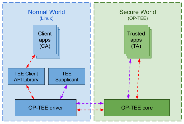
Workflow
The following diagram represents the communication flow between the normal and the secure worlds:
Source code
The source code for ConnectCore MP13 OP-TEE OS is available at https://github.com/digi-embedded/optee_os/tree/3.16.0/stm/maint.
This is forked from the SoC vendor (STMicroelectronics) repo, which is itself a fork of the original repo, hosted by Linaro. This repo contains the SoC customizations by STMicroelectronics as well as Digi customizations for the SOM.
Current supported version is 3.16.0.
Device tree configuration
The OP-TEE can manage its configuration with a device tree. This device tree includes the hardware required for the OP-TEE to work and defines the security rules to access secure peripherals from the normal world (U-Boot, Linux).
The device tree for the ConnectCore MP13 is available at https://github.com/digi-embedded/optee_os/blob/3.16.0/stm/maint/core/arch/arm/dts/ccmp13-dvk.dts
Secure services
In an SoC, the OP-TEE is responsible for accessing certain subsystems that are considered critical, such as:
-
Power State Coordination Interface (PSCI): controls the power management of the system
-
System Control and Management Interface (SCMI): controls reset, clocks, and power regulators
-
Boot and Security (BSEC), One-Time Programmable (OTP): control the boot and security mechanism and the NVMEM
-
Oscillator calibration: handles compensation mechanism to internal oscillators
-
Secure random: handles the true random number generator
-
Reset Clock Controller (RCC): controls reset signals and clock distribution
-
Power Control (PWR): controls power supply and wake-up signals
-
Power Domain: handles low power modes
OP-TEE uses internal Trusted Applications to manage these services. Linux can access these resources via SCMI channels. The connection between Linux drivers and OP-TEE OS is resolved through the device tree.
Example: Power regulator
Power regulators in OP-TEE are handled by the SCMI.
This excerpt of the ConnectCore MP13 Development Kit OP-TEE device tree represents the vdd_adc regulator, which powers the ADC subsystem:
&i2c4 {
	[...]
	pmic: stpmic@33 {
		 [...]
		regulators {
			[...]
			vdd_adc: ldo1 {
				regulator-name = "vdd_adc";
				regulator-min-microvolt = <3300000>;
				regulator-max-microvolt = <3300000>;

				standby-ddr-sr {
					regulator-off-in-suspend;
				};
				standby-ddr-off {
					regulator-off-in-suspend;
				};
			};
		};
	};
};

[...]

&scmi_regu {
	compatible = "st,scmi-regulator-consumer";

	[...]

	scmi_vdd_adc: voltd-vdd_adc {
		voltd-name = "vdd_adc";
		regulator-name = "vdd_adc";
	};
};
In this excerpt, the following lines are highlighted:
-
The PMIC regulator with its given name
-
The node that represents the
vdd_adcregulator through the SCMI
A Linux device driver that wants to use the ADC regulator will refer to it through the SCMI.
&scmi_regu {
	[...]
	scmi_vdd_adc: voltd-vdd_adc {
		voltd-name = "vdd_adc";
		regulator-name = "vdd_adc";
	};
};

&adc_1 {
	/* PA5 which is shared with MikroE PWM */
	pinctrl-names = "default";
	pinctrl-0 = <&ccmp13_adc1_pins>;
	vdda-supply = <&scmi_vdd_adc>;
	vref-supply = <&scmi_vdd_adc>;
	status = "okay";
};
In this excerpt (which is a combination of ConnectCore MP13 SOM and DVK device trees), the following lines are highlighted:
-
The ADC regulator within the SMCI framework
-
The use of the regulator in the ADC node
Digi Embedded Yocto recipe
The recipe that builds the OP-TEE is called optee-os-stm32mp and belongs to meta-st-stm32mp layer.
The OP-TEE OS is merged with U-Boot in the tf-a-stm32mp recipe, which produces a Firmware Image Program (FIP) binary called fip-ccmp13-dvk-optee.bin.
To build the FIP binary from within a Digi Embedded Yocto project:
$ bitbake tf-a-stm32mpRead more
You can read more on OP-TEE OS implementation for the STM32MP13 at https://wiki.st.com/stm32mpu/wiki/OP-TEE_overview
