

The NXP {cpu-family} CPU has eight GPIO ports. Each port can generate and control 32 signals.
The MCA also features a number of GPIO pins (multiplexed with Analog-to-Digital Converter (ADC) functionality). See MCA I/O pads for a list of all available MCA IOs and their capabilities.
GPIOs on the ConnectCore 8X platforms
-
On the ConnectCore 8X system-on-module:
-
Many, but not all, of the {cpu-family} GPIO ports and pins are available at the system-on-module, multiplexed with other functions (labeled GPIOx_IOy where x is the port and y is the GPIO pin). See Hardware reference manuals for information about what GPIO ports and pins are available and their multiplexed functionality.
-
19 MCA GPIO pins are available (labeled MCA_IOx where x is the GPIO pin).
-
-
On the ConnectCore 8X SBC Pro, the expansion connector allows direct access to several {cpu-family} GPIOs and MCA GPIOs.
GPIOs on the SOM and carrier board are used for many purposes, such as:
-
Power enable line for transceivers
-
Reset line for controllers
-
LCD backlight control
-
Interrupt line
-
User LED
-
User button
Kernel configuration
Support for {cpu-family} GPIOs is automatically provided through the non-visible option CONFIG_GPIO_MXC.
Kernel driver
The driver for the {cpu-family} GPIO is located at:
| File | Description |
|---|---|
{cpu-family} GPIO driver |
Device tree bindings and customization
The {cpu-family} GPIO device tree binding is documented at
Documentation/devicetree/bindings/gpio/fsl-imx-gpio.txt.
One GPIO controller is defined for each {cpu-family} GPIO port in the common {cpu-family} device tree file:
	gpio0: gpio@5d080000 {
		compatible = "fsl,imx8qm-gpio", "fsl,imx35-gpio";
		reg = <0x0 0x5d080000 0x0 0x10000>;
		interrupts = <GIC_SPI 136 IRQ_TYPE_LEVEL_HIGH>;
		gpio-controller;
		#gpio-cells = <2>;
		power-domains = <&pd_lsio_gpio0>;
		interrupt-controller;
		#interrupt-cells = <2>;
	};

[...]

	gpio7: gpio@5d0f0000 {
		compatible = "fsl,imx8qm-gpio", "fsl,imx35-gpio";
		reg = <0x0 0x5d0f0000 0x0 0x10000>;
		interrupts = <GIC_SPI 143 IRQ_TYPE_LEVEL_HIGH>;
		gpio-controller;
		#gpio-cells = <2>;
		power-domains = <&pd_lsio_gpio7>;
		interrupt-controller;
		#interrupt-cells = <2>;
	};
The ConnectCore 8X device tree include file and the carrier board device tree files use the {cpu-family} GPIOs.
For example, on the ConnectCore 8X, GPIO3_IO09 is used to activate internal circuitry during the MCA firmware update:
	mca_cc8x: mca@63 {
		compatible = "digi,mca-cc8x";
		reg = <0x63>;
		interrupt-parent = <&wu>;
		interrupts = <GIC_SPI 177 IRQ_TYPE_LEVEL_HIGH>;
		interrupt-controller;
		#interrupt-cells = <2>;
		fw-update-gpio = <&gpio3 9 GPIO_ACTIVE_LOW>;
		pinctrl-names = "default";
		pinctrl-0 = <&pinctrl_mca_cc8x>;

		[...]
};
For example, on the ConnectCore 8X SBC Pro, GPIO3_IO18 is used to reset the PHY of ENET1 Ethernet interface:
&fec1 {
pinctrl-names = "default";
pinctrl-0 = <&pinctrl_fec_mdio>,
<&pinctrl_fec_gpio>,
<&pinctrl_fec1_gpio>,
<&pinctrl_fec1>;
clocks = <&clk IMX8QXP_ENET0_IPG_CLK>,
<&clk IMX8QXP_ENET0_AHB_CLK>,
<&clk IMX8QXP_ENET0_REF_50MHZ_CLK>,
<&clk IMX8QXP_ENET0_PTP_CLK>,
<&clk IMX8QXP_ENET0_TX_CLK>;
phy-mode = "rgmii-id";
phy-handle = <ðphy1>;
phy-supply = <®_3v3_eth0>;
phy-reset-gpios = <&gpio3 18 GPIO_ACTIVE_LOW>;
phy-reset-duration = <1>;
fsl,magic-packet;
[...]
};IOMUX configuration
You must configure the pads that are to be used as {cpu-family} GPIOs. See Pin multiplexing (IOMUX).
For GPIOs that are managed by other drivers, you must configure their pad IOMUX inside the driver node specific pinctrl-0 to work according to the specified interface functionalities.
On the ConnectCore 8X example from above, mca_cc8x node configures pinctrl_mca_cc8x:
pinctrl_mca_cc8x: mcagrp {
	fsl,pins = <
		[...]

		/* MCA_FW_UPDATE */
		SC_P_QSPI0A_DATA0_LSIO_GPIO3_IO09	0x06000021
	>;
};
For GPIOs that are not associated with any interface or that can’t be handled by a driver, see Configure independent pin IOMUX and pad control. The following external pads are configured as GPIOs on the default device tree:
-
On the ConnectCore 8X SBC Pro expansion connector:
Pad Signal GPIO A7
GPIO4_21
GPIO4_IO21
B7
GPIO4_20
GPIO4_IO20
C4
SPI0_IRQ_N
GPIO1_IO01
C7
EXP_I2C_IRQ_N
GPIO3_IO15
C8
EXP_I2C_GPIO
GPIO3_IO14
C13
ADC_IN4
GPIO1_IO14
C14
ADC_IN5
GPIO1_IO13
C15
GPIO4_19
GPIO4_IO19
C18
GPIO0_12
GPIO0_IO12
D11
M40_UART_TX
GPIO1_IO11
D12
M40_UART_RX
GPIO1_IO12
D14
ADC_IN1
GPIO1_IO09
D19
GPIO5_09
GPIO5_IO09
GPIO pads power domains
The {cpu-family} GPIOs are configurable and can work at 1.8 V or 3.3 V depending on the power domain of the pad they are on.
You can access the GPIOs from your Android application. See GPIO API for more information about the GPIO APIx.
To determine the working voltage of a given GPIO:
-
Locate the pad of a given signal on the ConnectCore 8X SBC Pro schematics. For instance, on the ConnectCore 8X SBC Pro, signal
GPIO5_09comes from padENET0_REFCLK_125M_25Mof the ConnectCore 8X SOM: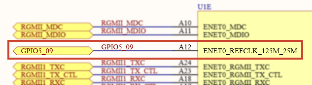
-
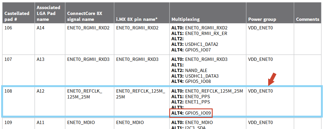
Locate this pad on the IMOUX section of the ConnectCore 8X Hardware Reference Manual. This table lists the associated GPIO of the pad, and the power domain it is on:
-
Locate the power domain (
VDD_ENET0on the example) on the ConnectCore 8X SBC Pro schematics. Here you can tell the voltage of the power domain: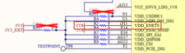
Using the GPIOs
You can access the GPIOs from your Android application. See GPIO API for more information about the GPIO APIx.
Calculate the Linux GPIO number of a GPIO pin
For each GPIO controller entry on the device tree, Linux creates an entry /sys/class/gpio/gpiochipN, where N is calculated as per the formula:
N = <n_gpios> * <port_index>
Each entry has the following read-only attributes:
-
base: same as N, the first GPIO managed by this chip
-
label: provided for diagnostics (not always unique)
-
ngpio: the number of GPIOs this controller manages (from N to N + ngpio - 1)
GPIOs on the ConnectCore 8X system-on-module
Every GPIO port of the {cpu-family} CPU is a different GPIO controller and thus has its own /sys/class/gpio/gpiochipN entry on the sysfs.
On the default ConnectCore 8X system-on-module device tree, the {cpu-family} CPU’s GPIO ports are probed first. Considering each one has 32 GPIOs, the formula results:
N = 32 * <port_index>
-
GPIO0:
/sys/class/gpio/gpiochip0 -
GPIO1:
/sys/class/gpio/gpiochip32 -
GPIO2:
/sys/class/gpio/gpiochip64 -
GPIO3:
/sys/class/gpio/gpiochip96 -
GPIO4:
/sys/class/gpio/gpiochip128 -
GPIO5:
/sys/class/gpio/gpiochip160 -
GPIO6:
/sys/class/gpio/gpiochip192 -
GPIO7:
/sys/class/gpio/gpiochip224
Calculate the Linux GPIO number for a certain GPIO pin by adding the GPIO pin index to the port base index. For instance:
{cpu-family} GPIO2_IO4 (port 2, pin 4) is: 64 + 4 = 68.
The following formula applies to {cpu-family} CPU GPIOs (without requiring the user to know the GPIO base of each port):
\$"LinuxGPIO_num" = 32 * "<port_index>" + "<gpio_pin>"\$
For instance, {cpu-family} GPIO2_IO4 (port 2, pin 4) is:
\$32 * color(red)(2) + color(red)(4) = 68\$
Sample application
The GPIO Sample Application demonstrates the usage of the GPIO API. In this example, one GPIO is configured as input and another as output. You can press the virtual button to switch on and off the User 0 LED corresponding to the output GPIO.
Go to GitHub to see the application instructions and source code.
See MCA General Purpose Input/Output (GPIO) for additional information on MCA GPIOs.
