

The I/O Expander is an integrated circuit on the ConnectCore 6UL SBC Pro carrier board. Digi programs firmware inside this chip on the ConnectCore 6UL SBC Pro boards, but if you decide to assemble this chip on your own carrier board the chip will initially be blank.
To program a blank I/O Expander for the first time, see Program firmware with JTAG debugger.
If the I/O Expander already has programmed firmware, check the firmware version using the sysinfo command.
| Before updating the firmware, verify the file you are going to program is a more recent version than the one you have already programmed. |
Check the latest I/O Expander firmware version on the ConnectCore 6UL product support page.
Firmware update application
Use the application ioexp_fw_updater to update a new *.bin firmware file.
The syntax is:
# ioexp_fw_updater -h
Update the firmware of the I/O Expander.

Copyright(c) Digi International Inc.

Version: 1.10

-f FILE, --file    Update firmware from binary FILE (Flash is fully erased).
-h, --help         Show this message.
-v, --version      Show current version of the tool.

The update process takes about 20 seconds to complete. Do not power off
the device during this time.
For example:
# ioexp_fw_updater -f ioexp_fw_file.bin
The update process may take 20 seconds or more - DO NOT POWER OFF OR RESET
\|
Do not abort the firmware update process If the process is interrupted during the write phase, the I/O Expander may be left in an inconsistent state. If the process fails, you can retry manually but success is not guaranteed. In this case, you can only recover the firmware with the JTAG debugger. See Program firmware with JTAG debugger. |
After a few seconds, the application finishes and returns to the prompt. After updating the firmware of the I/O Expander, the device does not restart automatically. Digi recommends a manual reboot to re-synchronize the device settings with its Linux driver.
Program firmware with JTAG debugger
This operation is only required when the I/O Expander IC is blank or its firmware cannot be updated with the ioexp_fw_updater software tool.
| Before programming via JTAG, verify that you can’t program the firmware using the updater application. See Firmware update application. |
To program the I/O Expander firmware using a JTAG debugger, you need:
-
A hardware debugger such as a P&E USB multilink debugger or a standalone Cyclone programmer.
-
An accessible Serial Wire Debug (SWD) port to the I/O Expander on your carrier board.
-
An adapter cable between the hardware debugger and the SWD port.
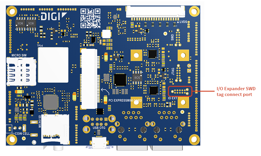
I/O Expander SWD port
The Digi ConnectCore 6UL SBC Pro board has tag connect footprints to access the SWD port of the I/O Expander:
| Pin | Line |
|---|---|
1 |
VCC |
2 |
SWD_DIO |
3 |
GND |
4 |
SWD_CLK |
5 |
VCC |
6 |
- |
7 |
- |
8 |
- |
9 |
- |
10 |
RESET_N |

Use the pinout as reference to create a custom cable between your debugger and the tag-connect footprint on the carrier board.
Program firmware with USB multilink debugger
The P&E USB Multilink debugger is a hardware debugger that you can drive from a host computer via USB.
To program firmware using this debugger:
-
You need a GDB server running on the debugger. Download and install NXP Kinetis Design Studio, which contains a GDB server for the P&E multilink debugger.
-
Download the ELF image from the ConnectCore 6UL product support page.
-
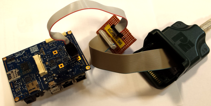
Connect the debugger to the PC via USB, and to the designated SWD port on the carrier board with the adapter cable. See SWD port for more information. You must hold the cable to keep it connected during the programming process. (The following image is included for general reference and may not match your board.)
-
Power on the board. Both LEDs on the debugger light up.
-
Run the Linux command line version of Kinetis Design Studio on your host computer with two parameters:
-
-startserverto start the P&E GDB server and -
-device=<model>to specify the Kinetis model you are connecting to (NXP_KL1x_KL14Z32M4for the I/O Expander,KL03: KL03P24M48SF0for the MCA).$ /opt/KDS_v3/eclipse/plugins/com.pemicro.debug.gdbjtag.pne_2.4.1.201603202153/lin/pegdbserver_console -startserver -device=<model>The server runs, detects the hardware, and lists the ports it is running on.
-
-
In another shell, source the Digi Embedded Yocto SDK environment:
$ source /opt/dey/3.2-r3/ccimx6ulsbc/environment-setup-cortexa7t2hf-neon-dey-linux-gnueabi -
Run the GDB client:
$ arm-dey-linux-gnueabi-gdb -
At the GDB prompt, connect to the GDB server on the debugger (using one of the ports reported above):
(gdb) target remote localhost:7224The server reports "Connection from "127.0.0.1" via 127.0.0.1"
-
Load the ELF file you want to debug/program with:
(gdb) load filename.elfThis erases and programs the flash and loads it with the file.
-
Continue execution of the loaded file with:
(gdb) continue -
Quit the GDB server by pressing CTRL+C.
-
The ELF file contains only the bootloader, not the full firmware. Once you install the bootloader, you can program the firmware using the application. See Update firmware.
-
When finished programming, restart to load the new firmware. Use the command
sysinfoto print the firmware version and verify correct programming.
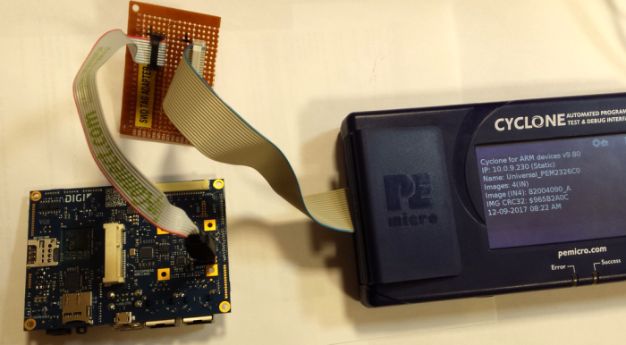
Program firmware with standalone Cyclone programmer
The P&E stand-alone Cyclone programmer is designed for programming in a production environment.
| The following instructions assume you have installed and configured your Cyclone programmer according to the manufacturer setup instructions. |
-
Download the desired SAP (Stand-Alone Programming) image from the ConnectCore 6UL product support page.
-
Transfer the image to the Cyclone programmer. After this step is done, you no longer need the host PC and you can program the firmware with a button press.
-
On the Cyclone programmer, use the screen menus to select the image to program.
-
Connect the Cyclone programmer to the designated SWD port on the carrier board with the adapter cable. See SWD port for more information. You must hold the cable to keep it connected during the programming process. (The following image is included for general reference and may not match your board.)
-
Power on the board.
-
Press the Start button on the Cyclone programmer and wait for the Success LED to light up.
-
When finished programming, restart the device to load the new firmware. Use the command
sysinfoto print the firmware version and verify correct programming.