

The NXP i.MX93 CPU has four GPIO ports. The number of GPIOs that each port can generate and control varies:
-
GPIO1: 16 signals
-
GPIO2: 30 signals
-
GPIO3: 32 signals
-
GPIO4: 30 signals
GPIOs on the ConnectCore 93 platforms
-
On the ConnectCore 93 system-on-module:
-
Many of the i.MX93 GPIOs are available at the system-on-module, multiplexed with other functions (labeled GPIOx_IOy where x is the port and y is the GPIO pin). See Hardware reference manuals for information about GPIO pins and their multiplexed functionality.
-
-
On the ConnectCore 93 Development Kit, the expansion connectors allow direct access to some of the i.MX93 GPIOs.
GPIOs on the SOM and carrier board are used for many purposes, such as:
-
Power enable line for transceivers
-
Reset line for controllers
-
Interrupt line
-
User LED
-
User button
|
The GPIO lines See Hardware reference manuals for information on the jumper connections and the multiplexed functionality they select. |
Kernel configuration
Support for i.MX93 GPIOs is automatically provided through the non-visible option CONFIG_GPIO_VF610.
Kernel driver
The driver for the i.MX93 GPIO is located at:
| File | Description |
|---|---|
i.MX93 GPIO driver |
Device tree bindings and customization
The i.MX93 GPIO device tree binding is documented at
Documentation/devicetree/bindings/gpio/gpio-vf610.yaml.
One GPIO controller is defined for each i.MX93 GPIO port in the common i.MX93 device tree file:
		gpio1: gpio@47400080 {
			compatible = "fsl,imx93-gpio", "fsl,imx7ulp-gpio";
			reg = <0x47400080 0x1000>, <0x47400040 0x40>;
			gpio-controller;
			#gpio-cells = <2>;
			interrupts = <GIC_SPI 10 IRQ_TYPE_LEVEL_HIGH>;
			interrupt-controller;
			#interrupt-cells = <2>;
			clocks = <&clk IMX93_CLK_GPIO1_GATE>,
				 <&clk IMX93_CLK_GPIO1_GATE>;
			clock-names = "gpio", "port";
			gpio-ranges = <&iomuxc 0 92 16>;
			npgios = <16>;
		};

		[...]

		gpio4: gpio@43830080 {
			compatible = "fsl,imx93-gpio", "fsl,imx7ulp-gpio";
			reg = <0x43830080 0x1000>, <0x43830040 0x40>;
			gpio-controller;
			#gpio-cells = <2>;
			interrupts = <GIC_SPI 189 IRQ_TYPE_LEVEL_HIGH>;
			interrupt-controller;
			#interrupt-cells = <2>;
			clocks = <&clk IMX93_CLK_GPIO4_GATE>,
				 <&clk IMX93_CLK_GPIO4_GATE>;
			clock-names = "gpio", "port";
			gpio-ranges = <&iomuxc 0 38 28>, <&iomuxc 28 36 2>;
			ngpios = <30>;
		};
For example, on the ConnectCore 93 Development Kit, GPIO2_IO22 is used to reset the camera:
	/* MIPI-CSI camera */
	ov5640_mipi: ov5640_mipi@3c {
		compatible = "ovti,ov5640";
		reg = <0x3c>;
		pinctrl-names = "default";
		pinctrl-0 = <&pinctrl_mipi>;
		clocks = <&mipi_csi_xtal24m>;
		clock-names = "xclk";
		csi_id = <0>;
		powerdown-gpios = <&gpio2 22 GPIO_ACTIVE_LOW>;
		mclk = <24000000>;
		mclk_source = <0>;
	[...]
};
IOMUX configuration
You must configure the pads that are to be used as i.MX93 GPIOs. See Pin multiplexing (IOMUX).
For GPIOs that are managed by other drivers, you must configure their pad IOMUX inside the driver node specific pinctrl-0 to work according to the specified interface functionalities.
For GPIOs that are not associated with any interface or that can’t be handled by a driver, see Configure independent pin IOMUX and pad control.
-
ULED/BUTTON1 is GPIO3_IO07
-
ULED/BUTTON2 is GPIO4_IO23
GPIO pads power domains
The i.MX93 GPIOs may work at 1.8 V or 3.3 V depending on the power domain of the pad they are on. To determine the working voltage of a given GPIO:
-
Locate the pad of a given signal on the ConnectCore 93 Development Kit schematics. For instance, on the ConnectCore 93 Development Kit, signal
CAN2_STBYcomes from padSPI1_SCK(pad E17) of the ConnectCore 93 SOM: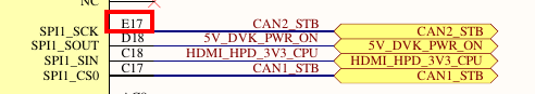
-
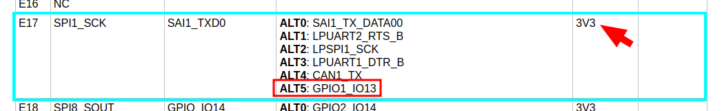
Locate this pad on the IOMUX section of the ConnectCore 93 Hardware Reference Manual. This table lists the associated GPIO of the pad, and the power domain it is on:
-
In the example, the power domain is 3V3. If a different power domain applies, locate it on the ConnectCore 93 Development Kit schematics to determine its voltage.
Use the GPIOs
The package libgpiod (added by packagegroup-dey-core) provides a set of tools (such as gpioget, gpioset, etc.) for controlling the GPIOs from user space.
| You can still control the GPIOs from the sysfs, but this ABI is not recommended. See https://www.kernel.org/doc/html/latest/admin-guide/gpio/sysfs.html. |
Detect GPIO ports
Use gpiodetect to list the GPIO ports detected by the kernel:
# gpiodetect
gpiochip0 [47400080.gpio] (16 lines)
gpiochip1 [43810080.gpio] (30 lines)
gpiochip2 [43820080.gpio] (32 lines)
gpiochip3 [43830080.gpio] (30 lines)
where:
-
Ports
gpiochip0togpiochip3are the i.MX93 GPIO ports.
This nomenclature corresponds with GPIO1 to GPIO4, as shown in the i.MX93 reference manual.
Information about a GPIO port
Use gpioinfo to list the lines of a given port:
# gpioinfo gpiochip1
gpiochip1 - 30 lines:
        line   0:      unnamed       unused   input  active-high
        line   1:      unnamed       unused   input  active-high
        line   2:      unnamed       unused   input  active-high
        line   3:      unnamed       unused   input  active-high
        line   4:      unnamed       unused   input  active-high
        line   5:      unnamed       unused   input  active-high
        line   6:      unnamed       unused   input  active-high
        line   7:      unnamed      "reset"  output   active-low [used]
        line   8:      unnamed       unused   input  active-high
        line   9:      unnamed       unused   input  active-high
        line  10:      unnamed "rs485-rts-gpio" output active-high [used]
        line  11:      unnamed       unused   input  active-high
        line  12:      unnamed   "spi0 CS0"  output   active-low [used]
        line  13:      unnamed       unused   input  active-high
        line  14:      unnamed       unused   input  active-high
        line  15:      unnamed       unused   input  active-high
        line  16:      unnamed       unused   input  active-high
        line  17:      unnamed       unused   input  active-high
        line  18:      unnamed  "interrupt"   input  active-high [used]
        line  19:      unnamed       unused   input  active-high
        line  20:      unnamed       unused   input  active-high
        line  21:      unnamed       unused   input  active-high
        line  22:      unnamed       unused  output  active-high
        line  23:      unnamed       unused   input  active-high
        line  24:      unnamed       unused   input  active-high
        line  25:      unnamed       unused   input  active-high
        line  26:      unnamed       unused   input  active-high
        line  27:      unnamed       unused   input  active-high
        line  28:      unnamed       unused   input  active-high
        line  29:      unnamed  "interrupt"   input  active-high [used]
Set an output high/low
Use gpioset to set a i.MX93 GPIO as output, such as GPIO1_IO27.
Use =1 to set it high, or =0 to set it low:
# gpioset gpiochip1 27=1
# gpioset gpiochip1 27=0
Read an input
Use gpioget to read the value of a i.MX93 GPIO input, such as GPIO1_IO27:
# gpioget gpiochip1 27
0
Use a GPIO as interrupt
Use gpiomon to wait for an event on a given GPIO, such as GPIO1_IO27:
# gpiomon --num-events 1 --rising-edge gpiochip1 27See the README of libgpiod for more information on the usage of these tools.
Sample application
An example application called apix-gpio-example is included in the dey-examples-digiapix recipe (part of dey-examples package) of the meta-digi layer.
This application shows how to manage GPIO lines using the Digi APIx library on the ConnectCore 93 platform.
|
By default, the Get Started with ConnectCore Cloud Services demo application seizes the user button.
To use the example, stop the |
Go to GitHub to see the application instructions and source code.
See GPIO API for more information about the GPIO APIx.
