

You can configure the MCA ADC lines to act as an analog window comparator and generate an IRQ depending on the voltage level in the input. This feature allows applications to be notified of this event instead of needing to periodically poll the input for its value.
Since this is an extension on the ADC driver, reading the input is also possible by using the same sysfs entry. The same formulas, channel mapping, and voltage reference also apply.
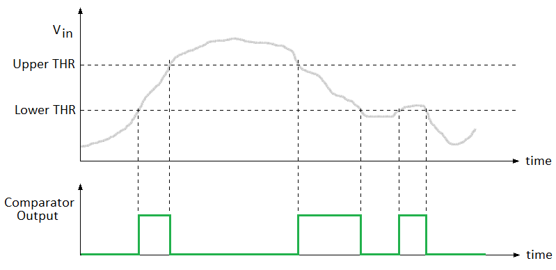
The comparator can be seen as a digital output that depends on two limits or thresholds: when the input is between the two limits the comparator’s output will be 1, and 0 when it is outside of the limits. If only one limit is needed, then the higher threshold should be set above the maximum (4096) and use the lower one.
The image below helps to illustrate when the edges are generated. Basically, entering the window generates a rising edge, and leaving it generates a falling edge, regardless of which threshold was exceeded (upper or lower).
Device tree bindings and customization
The MCA ADC device tree binding is documented at
Documentation/devicetree/bindings/iio/adc/digi,mca-adc.txt.
You can specify the list of channels you want to use as comparators with property digi,comparator-ch-list.
Both adc-ch-list and comparator-ch-list properties are exclusive.
If a channel is mistakenly included in both, adc-ch-list has priority and the kernel logs a warning.
|
MCA-enabled ADC channels and voltage reference
This example shows how to enable the analog comparator on one MCA ADC channel using the property digi,comparator-ch-list.
Rest of ADC channels are used as normal ADC channels.
The voltage reference property is the same for both ADCs and Comparators, refer to the ADC configuration chapter for more details on how to configure this property.
&mca_adc {
	digi,adc-ch-list = <8 14>;
	digi,comparator-ch-list = <7>;
	digi,adc-vref = <3000000>;
};
Using the comparators
The comparator driver is designed on top of the standard Industrial I/O (IIO) device drivers that can be accessed from the sysfs or from user applications.
Sysfs access
When configured as analog comparator, the MCA ADC driver creates the corresponding device entries in the IIO sysfs directory (/sys/bus/iio/devices).
Find the IIO sysfs path that corresponds to the MCA ADC (the one whose name is mca-cc8x-adc):
# cat /sys/bus/iio/devices/iio\:device0/name
mca-cc8x-adc
In this example, device0 corresponds to the MCA ADC.
The driver creates the following file entries per analog comparator channel, where X is the channel number:
-
in_voltageX_raw: reads the raw value from the input. This behaves the same as it does for the regular ADC driver. -
in_voltageX_cmp_thr_h: the upper threshold for the comparator window. It must be a decimal value between 0 and 4095. For example, for half of the voltage reference it should be 4095 / 2 = 2047. -
in_voltageX_cmp_thr_l: the lower threshold for the comparator window. It must be a decimal value between 0 and 4095. For example, for a quarter of the voltage reference it should be 4095 / 4 = 1023. -
in_voltageX_cmp_out: the output of the comparator. It is a read-only entry which returns 1 when the input is between the thresholds and 0 when it is outside. -
in_voltageX_cmp_rate: the sample rate for the comparator in sleep mode. The unit is 10 MCA timer ticks, each tick being 1/1024 second, or 0.976 milliseconds. For example, writing a 100 would make the MCA sample the input about once per second and update the comparator output. -
in_voltageX_cmp_edge: configures the edges that will trigger the comparator interrupt: it can beboth,rising,falling, ornone. -
in_voltageX_averager: the driver will sample the input the number of times configured here and average the result to increase the number of effective bits. By default it is 1 (no averaging) and it can be set to 1, 2, 4 or 8. Notice that this also increases the time for sampling and power consumption in sleep. Also, this does not affect the value returned byin_voltageX_raw, which is always a non-averaged sample. -
in_voltageX_wakeup: whether the comparator should keep running on suspend and poweroff mode. If enabled, it can be used as a wake-up source. It can be set toenabledordisabled.
Sample configuration
The following script configures channel 3 analog comparator as follows:
-
Sample once every 100 ms
-
Set upper threshold of 2 V. Considering a voltage reference of 3 V that is:
\$(2 * 4095) / 3 = 2730\$
-
Set lower threshold of 1 V. Considering a voltage reference of 3 V that is:
\$(1 * 4095) / 3 = 1365\$
-
Generate an interrupt on rising and falling edges.
-
Enable it to wake up the system from suspend or poweroff.
# Sample every 100 ms
echo 1 > /sys/bus/iio/devices/iio\:device0/in_voltage3_cmp_rate

# Set high threshold to 2/3 of the voltage reference
echo 2730 > /sys/bus/iio/devices/iio\:device0/in_voltage3_cmp_thr_h

# Set high threshold to 1/3 of the voltage reference
echo 1365 > /sys/bus/iio/devices/iio\:device0/in_voltage3_cmp_thr_l

# Enable IRQ on both edges
echo both > /sys/bus/iio/devices/iio\:device0/in_voltage3_cmp_edge

# Enable this comparator to operate on suspend
echo enabled > /sys/bus/iio/devices/iio\:device0/in_voltage3_wakeup
Sample application
An example application called adc_cmp_sample is included in the dey-examples package of meta-digi layer.
This application shows how to subscribe for comparator IRQs and decode them.
To see the syntax of the application, run:
# adc_cmp_sample --helpFind the source code of the application under
${DEY_INSTALL_DIR}/sources/meta-digi/meta-digi-dey/dey-examples/files/adc_cmp_sample/
and the recipe at
${DEY_INSTALL_DIR}/sources/meta-digi-dey/recipes-digi/dey-examples/dey-examples-adc-cmp.bb.
