The basic concept behind A/Ds or ADCs (Analog to Digital Converters) is to allow the analog signals to be converted to a digital format that can be easily read/transmitted in digital form. The XBee and XBee-PRO have integrated A/Ds that allow the module to be connected directly to analog devices like sensors, and send the data in serial form.
Enabling the A/Ds:
The 802.15.4 XBee has 6 usable A/D pins on it that allow the user to select one or all of those A/Ds (assuming sufficiently slow sample rates are chosen i.e. 1KHz/6 = 167Hz). The A/D feature can be enabled with the ATDx=2 command where x= 0-5(the A/D pin you wish to use). In order for the module to be able to read analog signals Vref must be tied to an appropriate voltage (0 < Vref <= Vcc).
Sample Rate:
Once the particular pin is enabled then the appropriate sample rate must be chosen, the maximum sample rate that can be achieved while using one A/D is 1sample/ms or 1KHz. The sample rate can be set with the ATIR command and is set in units of ms, so ATIR=0xA is a sample rate of 10ms or 100Hz.
Samples Before Transmission:
The XBee allows user to set the number of samples to be taken before the data is transmitted, this command is ATIT. The XBee can buffer up to 93 bytes worth of sample data, since the XBee uses a 10bit A/D converter each sample uses two bytes. This leads to a maximum buffer size of 46 samples or ATIT=0x2E.
UART Data:
On the receiving XBee the module has to be set up to receive the incoming RF packets over the UART. By setting ATIU=0x1 the receiving module will output the incoming serial data to the UART for you to read.
PWM Data:
There is also the option of translating that incoming data to a PWM (Pulse Width Modulation) so that the output can be translated back into analog form. In order to enable PWM output then set ATP0 and/or ATP1 equal to 2 (this will only convert for A/D-0 and A/D-1 respectively).
Example:
As an example for a simple A/D link the radios could be set as follows:
| Base |
Remote |
| DL = 5678 |
DL = 1234 |
| MY = 1234 |
MY = 5678 |
| P0 = 2 |
D0 = 2 |
| P1 = 2 |
D1 = 2 |
| IU = 1 |
IR = 14 |
| IA = 5678 (or FFFF) |
IT = 5 |
These settings will set the remote to sample ADC0&ADC1 once each every 20ms. It will then buffer 5 samples each before sending them back to the base. That should lead to the base receiving a 32 byte transmission (20 bytes data and 12 bytes framing) every 100ms.
UART Output:
When UART data is received the data is framed using our API structure. When the data is sent out the UART the data is automatically in API format, so the API doesn't need to be enabled. Notice how the data is listed from lesser ADCs to greater ADCs (ADC0 then ADC1 then ADC2 etc...). Below is an example of an API packet with ADC0 & ADC1 data:
7E 00 1C 83 56 78 22 00 05 06 00
00 00 03 FF 00 00 03 FF 00 00 03 FF 00 00 03 FF 00 00 03 FF 77
Where the UART API data stream can be broken down as:
| 7E |
Start Delimiter |
| 00 1C |
Length Bytes |
| 83 |
API Identifier Byte for 16bit A/D data (82 is for 64bit A/D data) |
| 56 78 |
Source Address Bytes |
| 22 |
RSSI Value Bytes |
| 00 |
Option Byte |
| 05 |
Sample Quantity Byte |
| 06 00 |
00000110 00000000 Channel Indicator * |
| 00 00 |
Sample Data ADC0 (min value for A/D is 00 00) |
| 03 FF |
Sample Data ADC1 (max value for A/D is 03 FF, indicating the value of ADC1 is Vref) |
| 77 |
Check Sum |
* bit field where the bits line up as (Ax=ADCx & Dx=DIOx):
| 0 |
0 |
0 |
0 |
0 |
1 |
1 |
0 |
0 |
0 |
0 |
0 |
0 |
0 |
0 |
0 |
| NA |
A5 |
A4 |
A3 |
A2 |
A1 |
A0 |
D8 |
D7 |
D6 |
D5 |
D4 |
D3 |
D2 |
D1 |
D0 |
PWM Output:
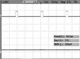
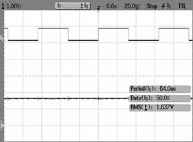
The PWM output will look like this:
ADC1=0.3V
ADC1=1.64V
ADC1=3.0V
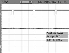
You will notice from the Oscilloscope traces that the duty cycle of PWM1 is directly proportional to the Voltage at ACD1 (assuming that I have set P1=2).