Table of Contents 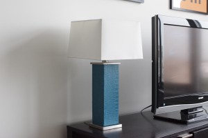
- Introduction
- Assemble the Parts
- Configure the Radios
- Wire up the Circuit
- Install the Digi XBee Internet Gateway
- Setup Digi Remote Manager
- Upload PHP Scripts
- Use it!
1) Introduction
In this example, we'll walk you through the steps for setting up the Digi XBee Internet Gateway and Digi Remote Manager (DRM) to control a lamp over the internet! Of course, you don't have to use a lamp for this; you can use XIG and Digi Remote Manager to control many kinds of devices and even read wireless sensors.
When you want to turn the lamp on or off, you'll click a bookmark on your bookmarks bar that will connect you to your own PHP-enabled web server. The server will send an XML-formatted request to Digi Remote Manager, which will pass the request along to the Digi XBee Internet Gateway. The XIG will wirelessly set the command on the Digi XBee to set a pin high, which is connected to a PowerSwitch Tail. The lamp connected to the PowerSwitch Tail will light up when the Digi XBee's pin is high.
2) Assemble the Parts
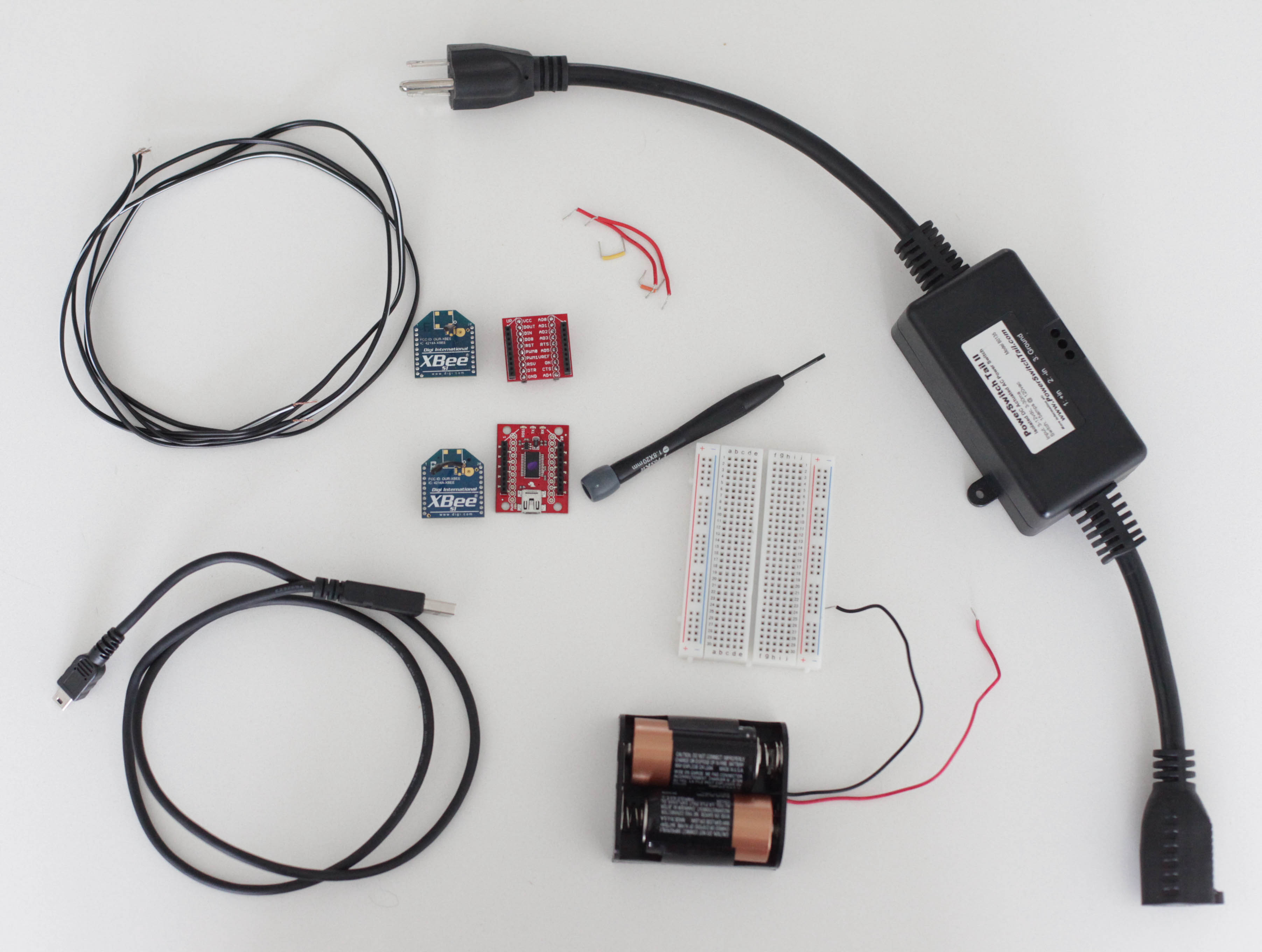
To connect a lamp to the internet via Digi Remote Manager, you'll need:
- 2 Digi XBee 802.15.4 Radios
- Access to a web server with PHP - There are many inexpensive web hosting plans out there and even the cheapest ones are usually PHP-enabled. Your internet service provider may even offer hosting service. If you're only interested in controlling your lamp from your local network, you can setup a computer with a web server to host the script.
- A Digi Remote Manager account - it's free!
- PowerSwitch Tail II - You can use the previous version if it's all you have, but it will require more circuitry to actuate the relay.
- Hookup wire - We'll be using a spool of two conductor wire to connect the PowerSwitch Tail to our circuit.
- Small, flat-head screwdriver
- Breadboard
- Jumper cables
- XBee Breakout Board - for your circuit.
- XBee Explorer USB - for programming your radios and for the Digi XBee Internet Gateway
- USB A to Mini-B Cable.
- A DC power source, 2.8 - 3.3V - For this build, we'll be using two C batteries in a battery holder from Radio Shack. You'll probably want to find a plug-in DC power source so that you can leave it plugged in and powered on.
3) Configure the Radios
If you're not familiar with configuring radios using AT commands, review the steps in the Basic Digi XBee 802.15.4 Chat tutorial, which walks you through configuring CoolTerm to program the radios.
Program the PowerSwitch Tail Radio
This is the radio that will receive commands and, in turn, activate the PowerSwitch Tail to turn the lamp on.
- Label one Digi XBee with "PST," insert it into the Explorer USB, and connect it to your computer.
- Launch CoolTerm and connect to the Digi XBee.
- Here are the commands we're going to use to configure the radio:
| Function |
Command |
Parameter |
| Reset |
ATRE |
N/A (resets the radio to its factory settings) |
| PAN ID |
ATID |
3001 (any address from 0 to FFFE will do) |
| MY Address |
ATMY |
2 |
| Pin 0 I/O configuration |
ATD0 |
4 (digital output, low on startup) |
| I/O input address |
ATIA |
0 (the default ATMY address of the XIG radio) |
| Write to memory |
ATWR |
N/A (save the settings to flash memory) |
- Here's what your terminal session might look like. The user input is in bold:
+++
OK
ATRE
OK
ATID 3001
OK
ATMY 2
OK
ATD0 4
OK
ATIA 0
OK
ATID
3001
ATMY
2
ATD0
4
ATIA
0
ATWR
OK
Note: Remember to issue the ATWR command when you're done so that the settings are saved in the radio's flash memory. If you don't issue this command, the radio will revert to its old settings when it loses power.
Program the XIG Radio
This is the radio that will act as the gateway between the internet and your Digi XBee network using XIG, the Digi XBee Internet Gateway.
- Label the other Digi XBee with "XIG," insert it into the Explorer USB and connect it to your computer.
- Launch CoolTerm and connect to the XBee.
- Here are the commands we're going to use to configure the radio:
| Function |
Command |
Parameter |
| Reset |
ATRE |
N/A (resets the radio to its factory settings) |
| PAN ID |
ATID |
3001 (any address from 0 to FFFE will do) |
| API Mode |
ATAP |
1 (basic API mode) |
| Pin 6 I/O configuration |
ATD6 |
1 (RTS monitoring disabled) |
| Serial baud rate |
ATBD |
6 (57,600 bps) |
| Write to memory |
ATWR |
N/A (save the settings to flash memory) |
- Here's what your terminal session might look like. The user input is in bold:
+++
OK
ATRE
OK
ATID 3001
OK
ATAP 1
OK
ATD6 1
OK
ATBD 6
OK
ATID
3001
ATAP
1
ATD6
1
ATBD
6
ATWR
OK
Note: Now that you've changed the baud rate on the XIG radio, you'll have to update the connection settings in CoolTerm if you decide to reconnect to adjust that radio's settings.
4) Wire up the Circuit
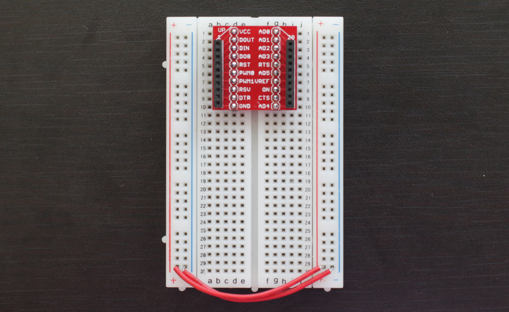
- Place the Digi XBee adapter into the breadboard and wire up the power buses to each other.
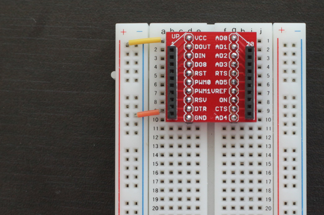
- Connect the VCC terminal of the Digi XBee adapter to the positive rail and the ground terminal to the negative rail.
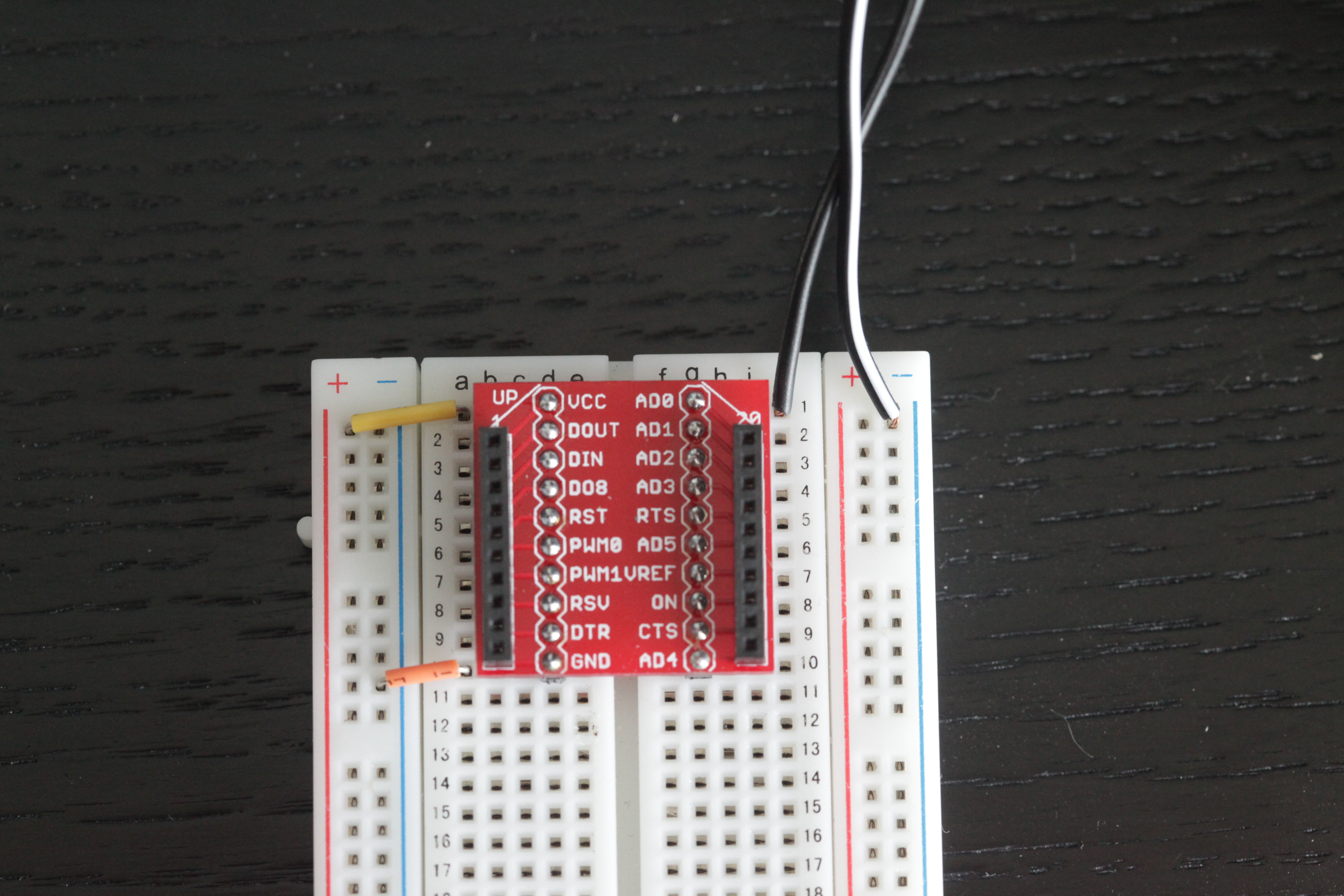
- Connect one of the of the hookup wires to I/O pin 0, which is physical pin 20, on the top right side of the Digi XBee. A second strand of wire gets connected to the ground bus.
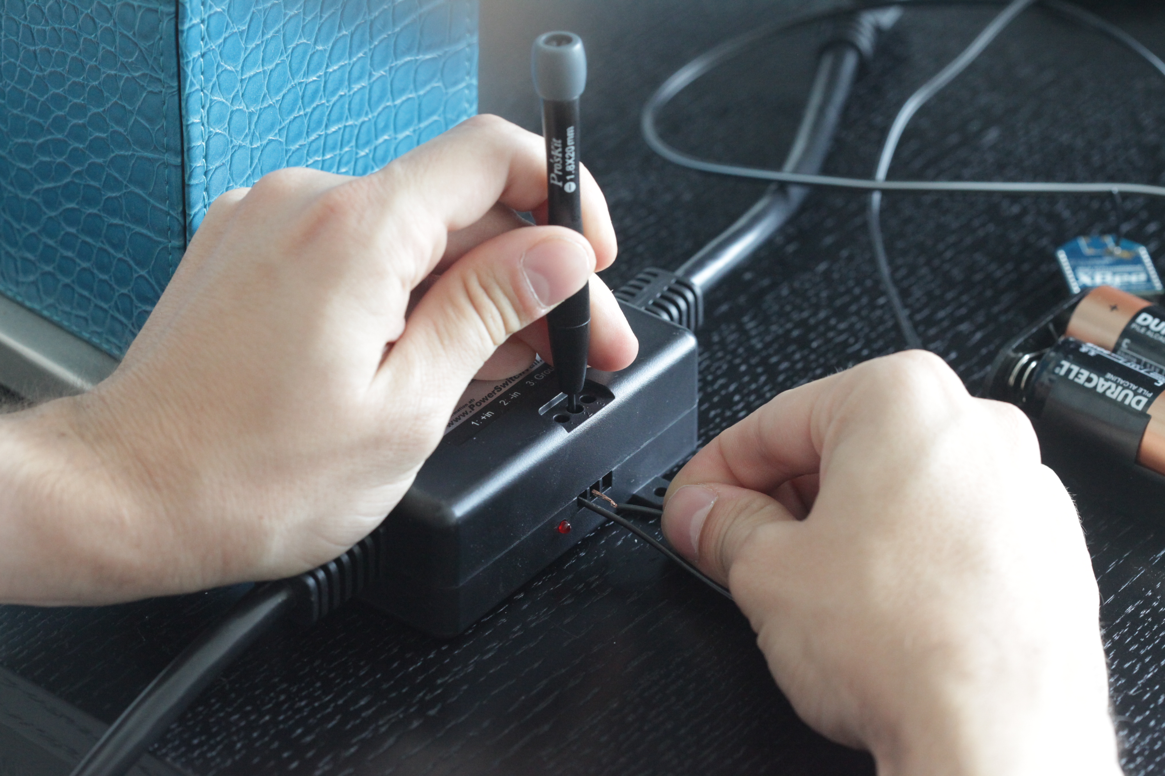
- Use the wire from the the Digi XBee's I/O pin 0 to connect it to the terminal marked "+in" on the PowerSwitch Tail. You'll need to use a small, flat-head screwdriver to loosen the screw terminal inside the PowerSwitch tail and to tighten it onto the wire. The wire from the breadboard's ground bus gets connected to "-in" on the PowerSwitch tail.
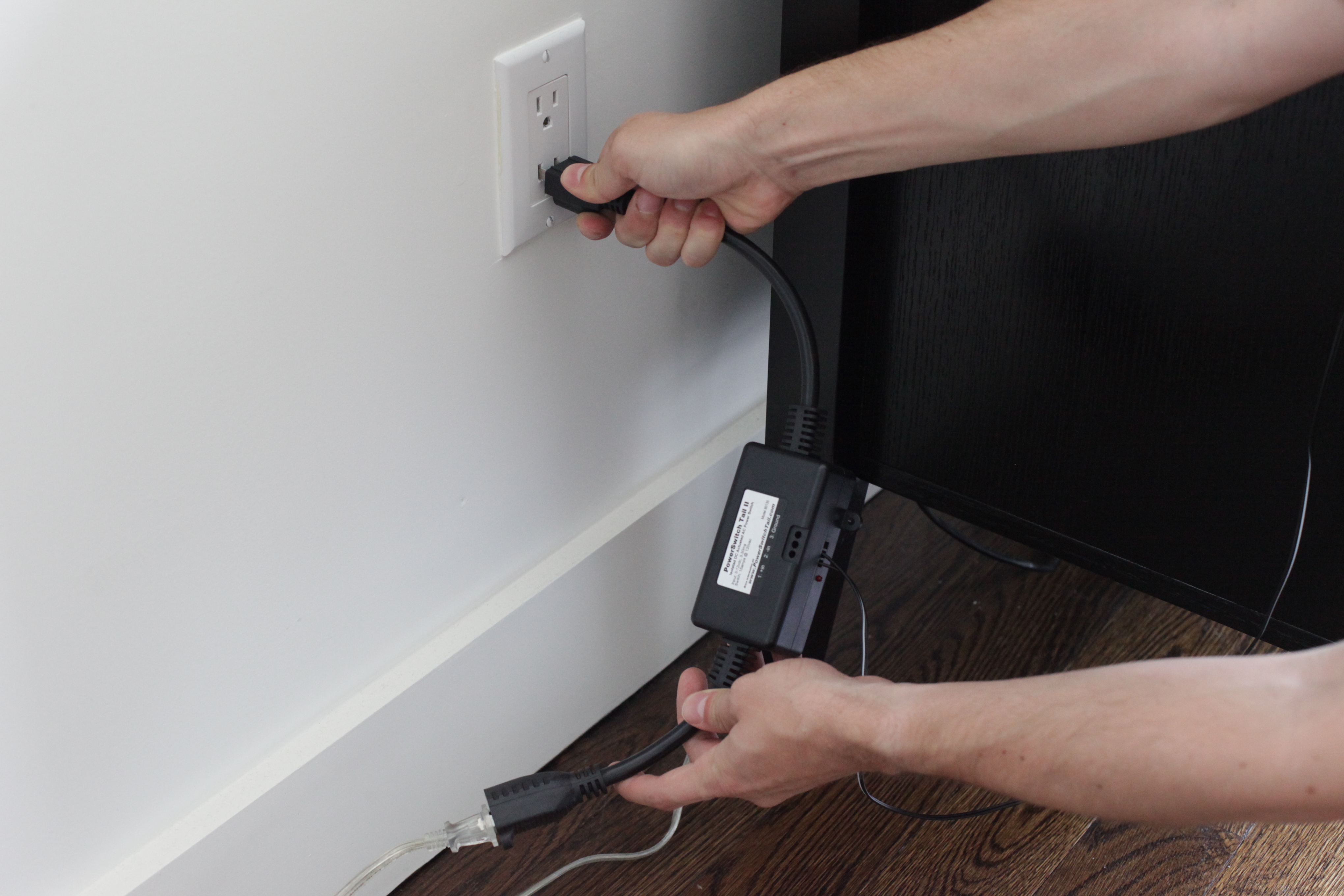
- Plug your lamp into the PowerSwitch Tail and plug the PowerSwitch Tail into the wall. Make sure the switch on your lamp is switched on.
-
- Write down the hardware address on the bottom of the radio. It will always start with "0013A200" and have 8 more digits from 0 to 9 or letters A to F (it's in hexadecimal). This is the address we'll use to control the radio through Digi Remote Manager.
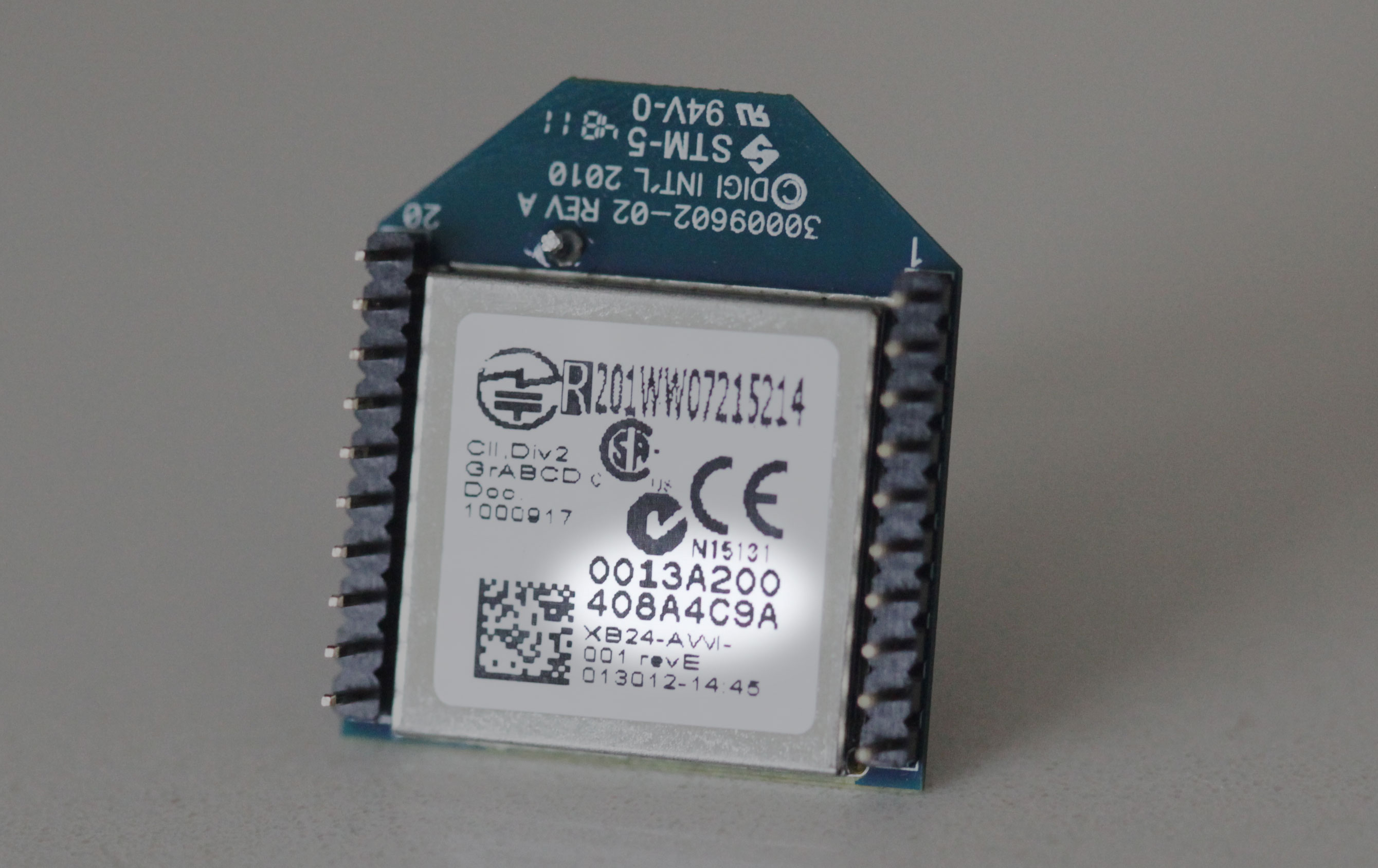
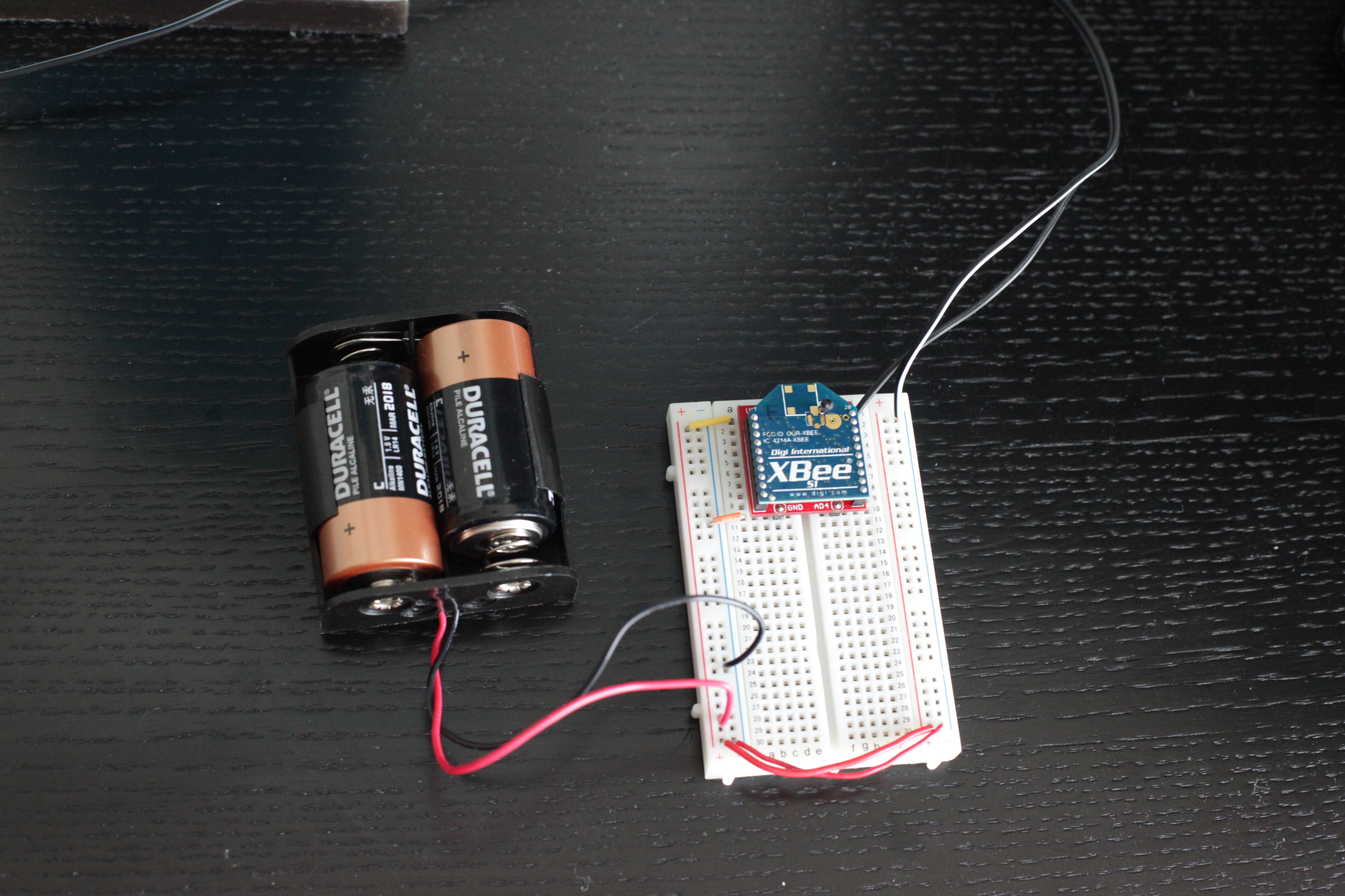
- Insert the Digi XBee into the adapter and connect your power source. We're using batteries for now, but if you want to leave this on all the time, you'll want to find a plug-in AC to DC adapter.
- Since we set the I/O mode of the pin to be low on start up with the command "ATD0 4", the PowerSwitch Tail will be off by default. If you'd like the lamp to be turned on when the Digi XBee is powered on, you can use the command "ATD0 5".
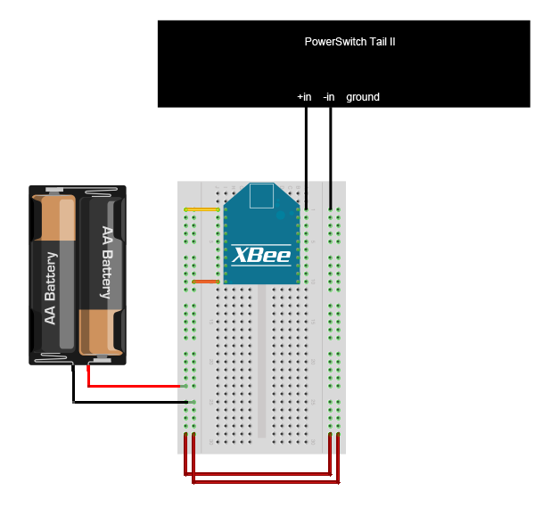
- Above is a diagram of the circuit. As mentioned before, you'll probably want to use a power source that plugs into the wall instead of batteries.
5) Install the Digi XBee Internet Gateway
- Download and install the Digi XBee Internet Gateway for your platform. Software installation instructions are available for Windows, OS X and Linux.
- Insert your XIG-labeled Digi XBee into the USB Explorer and connect it to your computer. Be sure you've disconnected your CoolTerm session.
-
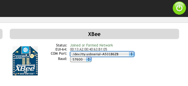
- Launch the XIG application, which will open your web browser and connect it to http://localhost:8000/. Choose the appropriate COM port and set the baud rate to 57600.
- If the power button in the upper right corner is red, click it so that it turns green and activates the XIG.

- Type in a description for your XIG and keep this page open for now, you'll need to copy the Device ID into Digi Remote Manager in the next step.
6) Setup Digi Remote Manager
Add Your XIG to Digi Remote Manager
- Log in to your Digi Remote Manager account. If you don't already have one, you can register for free.

- Click the tab labeled Digi Remote Manager and under the sub-tab Devices, click the plus button on the toolbar to add a device.
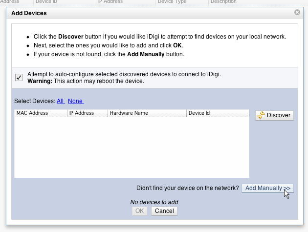
- An "Add Devices" window will appear. Click the button "Add Manually" and choose "Device ID" from the drop down box.
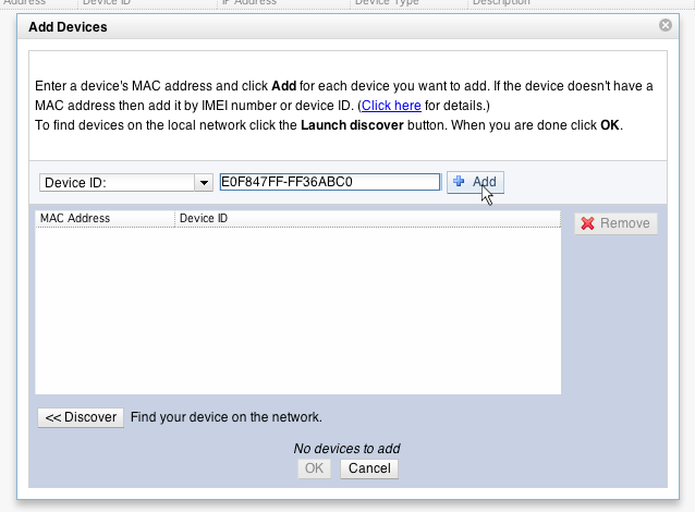
- Paste in the Device ID from your XIG set up page and click "Add." Then click "OK."

- You should then see the XIG—complete with the description you assigned it—in your devices list in Digi Remote Manager.
Sending a Remote AT Command via Digi Remote Manager
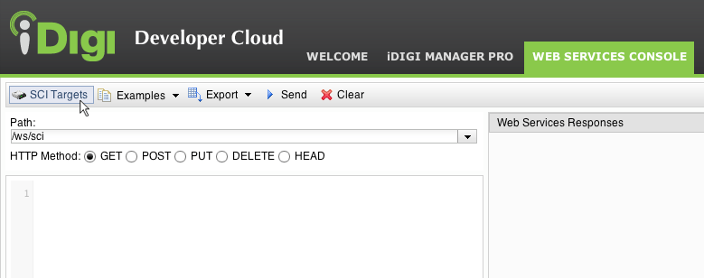
- Click on the "Web Services Console" tab and click the toolbar button labeled "SCI Targets"

- Choose the Device ID that matches your XIG and click "Add." Click "OK" to dismiss the window.
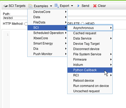
- Under the "Examples" menu, choose "SCI" and then "Python Callback," which will show you a template to send a command to the radio. As you can see, the Device ID of the gateway has been filled in for you:
<sci_request version="1.0">
<send_message>
<targets>
<device id="00000000-00000000-E0F847FF-FF36ABC0"/>
</targets>
<rci_request version="1.1">
<do_command target="rci_callback_example">
ping
</do_command>
</rci_request>
</send_message>
</sci_request>
- We're going to make a few changes to this example, emphasized in bold below. Replace the do_command target parameter with "xig" and replace the text "ping" with an "at" tag. Be sure to use the hardware address from the bottom of the PowerSwitch Tail's XBee in the hw_address parameter in the "at" tag. For formatting the hw_address, follow the pattern in the example below, with colons between pairs of digits and don't forget the exclamation point at the end!
<sci_request version="1.0">
<send_message>
<targets>
<device id="00000000-00000000-E0F847FF-FF36ABC0"/>
</targets>
<rci_request version="1.1">
<do_command target="xig">
<at hw_address="00:13:a2:00:40:8A:4C:9A!" command="D0" value="5" apply="true" />
</do_command>
</rci_request>
</send_message>
</sci_request>
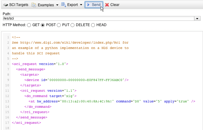
- Make sure "POST" is selected as the HTTP method.
- When you click "Send," your PowerSwitch Tail should actuate and the lamp will turn on! (You may need to enter your Digi Remote Manager credentials again.) To turn it off again, change the value parameter in the "at" tag to 4 and press send again.
- If nothing happened, here are a few trouble shooting steps:
- Under the section "Web Services Responses," click "examine." The response result should be "ok" and that means that Digi Remote Manager was able to send the command to the PowerSwitch Tail's Digi XBee. If that's the case, check your circuit. Perhaps review the more basic PowerSwitch Tail and digital input with a button examples to ensure all the parts work.
- If the response value is something along the lines of "error setting DDO parameter," that means that Digi Remote Manager wasn't able to find that hardware address. Check to make sure that you've got it right and that the target Digi XBee is powered on and configured correctly.
- If the response value is something along the lines of "name not registered," that means that Digi Remote Manager wasn't able to find the XIG. Make sure it's up and running correctly.
- If you got it working, great! You're now controlling your lamp over the internet! However, it doesn't make much sense to log into Digi
Remote Manger just to turn a lamp on, so we're going to set up a PHP script that will send this code to Digi Remote Manager automatically. Keep reading for how to do that!
7) Upload PHP Scripts
-
- Download the PHP code here and open it in your text editor. (local zip)
- Update the values at the top of the file to match your settings:
- Save the file and upload it somewhere within your webserver's document root so that you can access it via a URL.
- Access that URL to turn the lamp on and off using the "set" parameter:
- http://www.yourdomain.com/lamp.php?set=on
- http://www.yourdomain.com/lamp.php?set=off
- Drag each of those URLs to your bookmarks bar for convenient access!
Note: When you've confirmed that you have it working, you'll want to take appropriate steps to secure this page so that unauthorized people don't start messing with your lights! Look into setting up your server for basic authentication if you're using Apache as your web server.
8) Use it!
Now that you know how to control the digital output of an Digi XBee radio over the internet via Digi Remote Manager and XIG, take a look at our other examples for the other cools things you can control!