Table of Contents
- Introduction
- Assemble the Parts
- Configure the Radio
- Wire up the Circuit
- View it!
- Use it!
1) Introduction
When it comes to analog input, it doesn't get any easier than a basic potentiometer. Nicknamed "pots," these components are variable resistors. With a twist of their knob, you alter the amount of voltage that flows out through their center pin. If you've ever adjusted a volume dial, chances are, you were using a potentiometer. Potentiometers can be used for setting a level, determining an angle, or just as a simple user interface adjustment. Because you can set them immediately to a value that they'll hold indefinitely, pots are terrific for prototyping and testing. Use them as a stand-in for any kind of analog input. Let's get started and add them to your development toolkit!
4) Wire up the Circuit
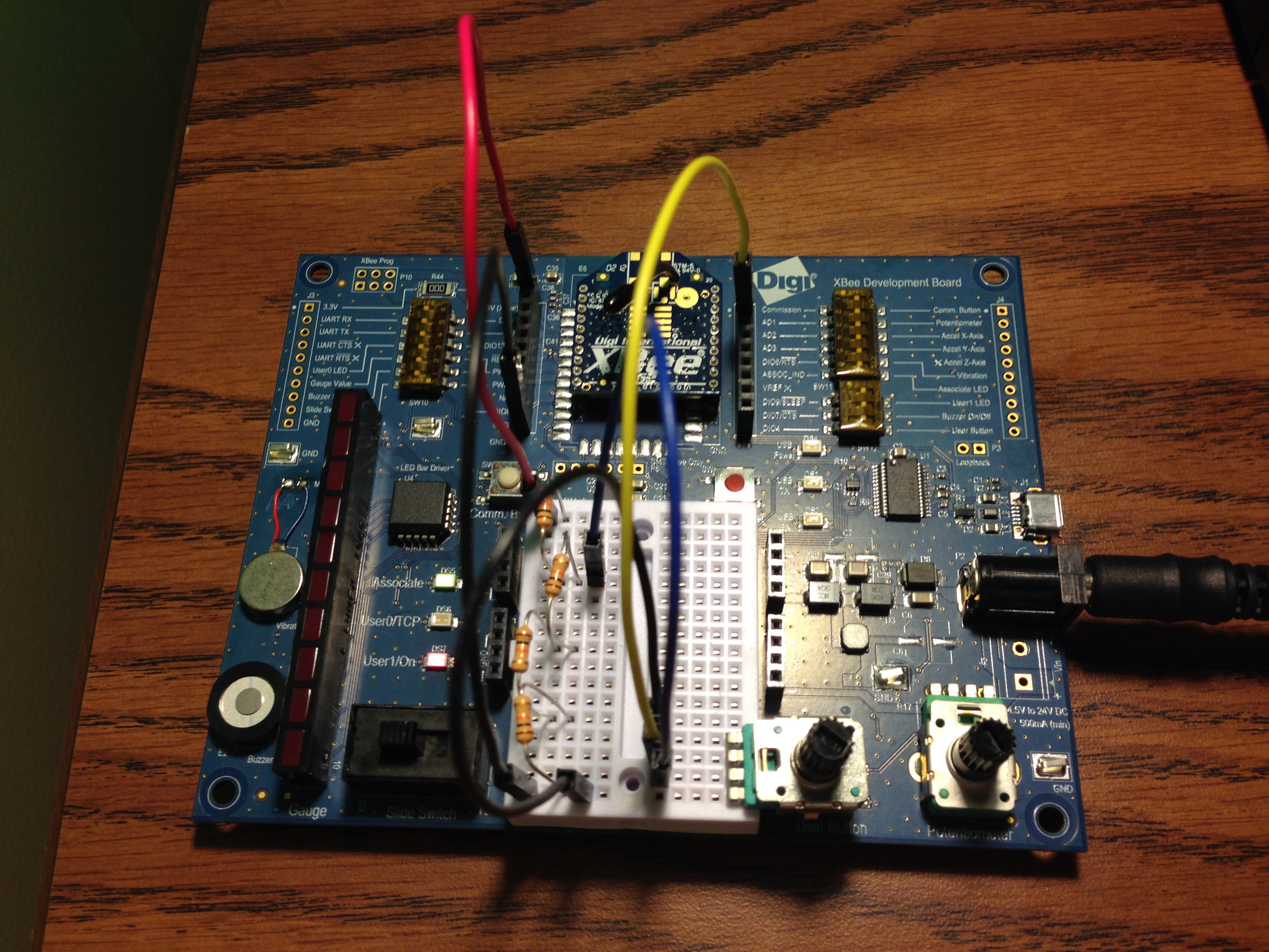
You will build this sensor circuit using the Digi XBee Development Board.
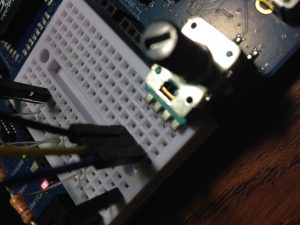
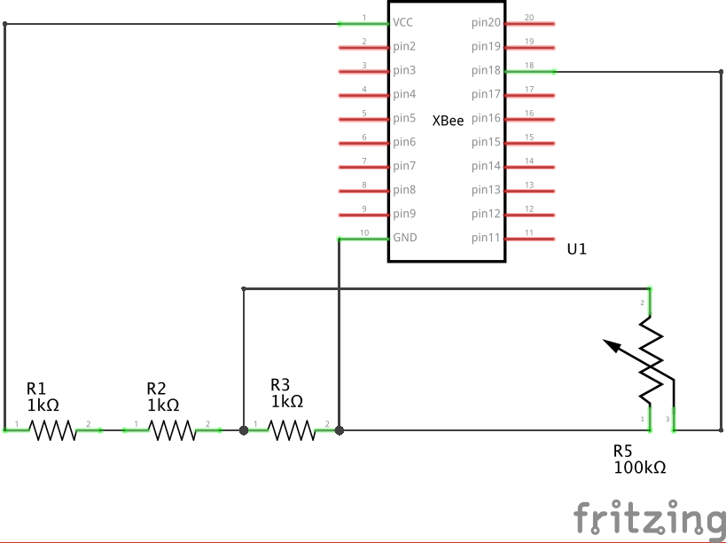
- Plug the potentiometer into the breadboard as shown. It has four pins. When facing the pins, they are from left to right:
- Pin 1: Ground.
- Pin 2: Output voltage that varies with the position of the knob.
- Pin 3: Voltage in, which we will feed with 1 volt.
- Pin 4: This is just a dummy pin and is not used for anything.
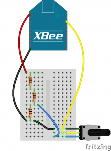
- Connect a black jumper wire from the potentiometer's pin 1 to ground (GND) as shown.
- Connect one end of a yellow (or any other color) jumper wire to the second pin (2) of the potentiometer. Connect the other end of this wire to to the XBee's AD1 pin.
- Plug in the four resistors to separate rows of the breadboard as shown. They will form a chain with the each resistor connecting to one end of each resistor on either side. We will use them to scale the input down from 3.3 volt input to the 1 volt maximum of the Digi XBee Zigbee's ADC.
- Connect a red wire from 3.3V to the open end of the first resistor.
- Connect a blue (or other color) jumper wire so that the third pin (3) of the potentiometer is connected to the junction between the first and second resistor as shown.
- Use a black wire to connect the open end of the fourth resistor to GND.
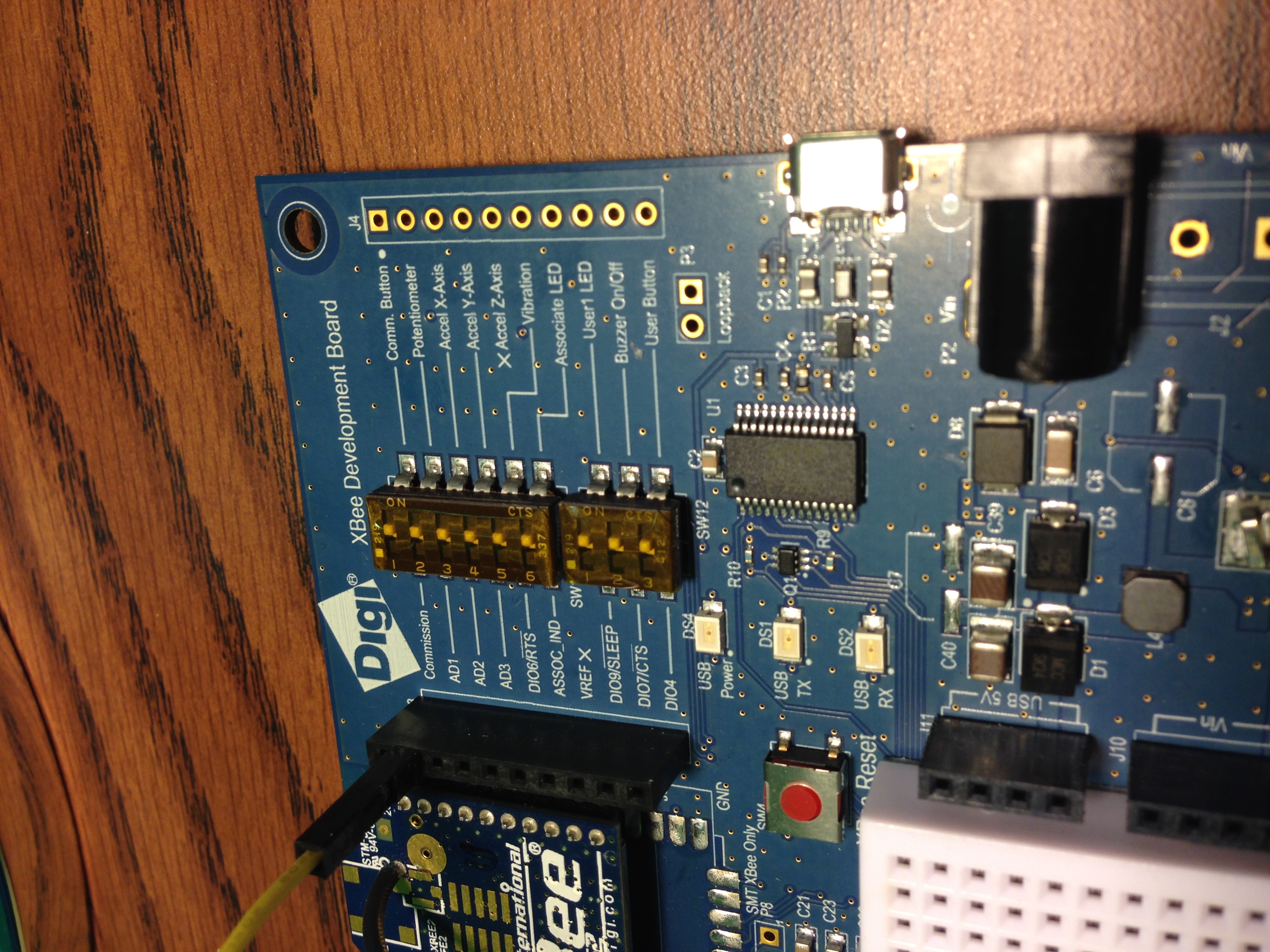
- Set the DIP switch for AD1 on the PCB to OFF to disconnect the soldered-on component.
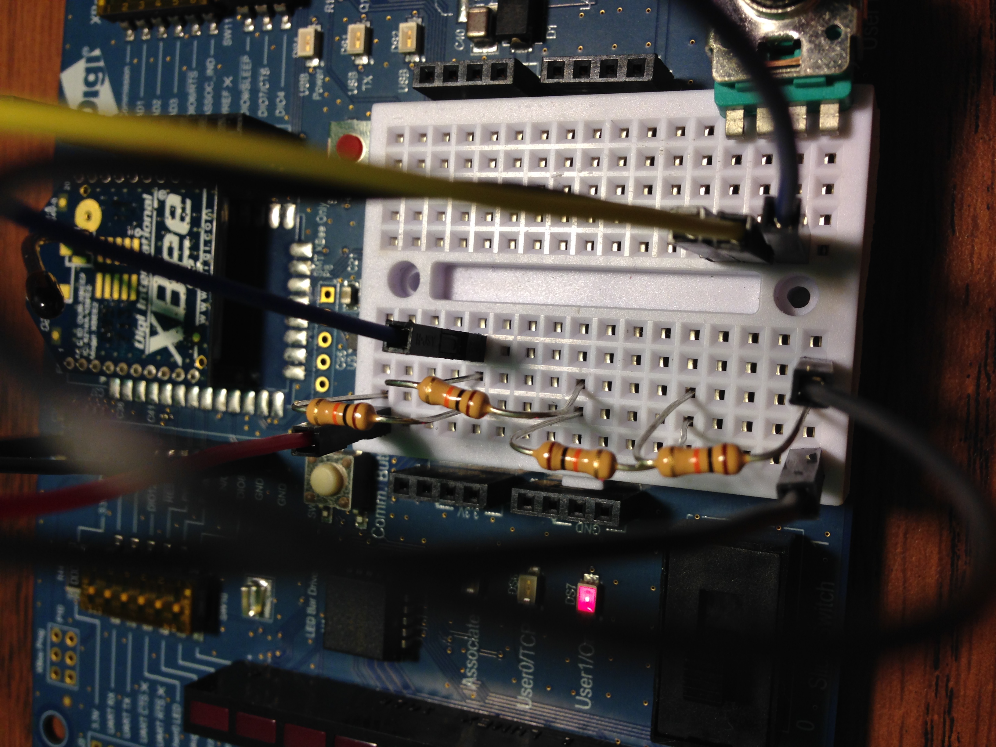
- Here's what everything should look like:
5) View It!
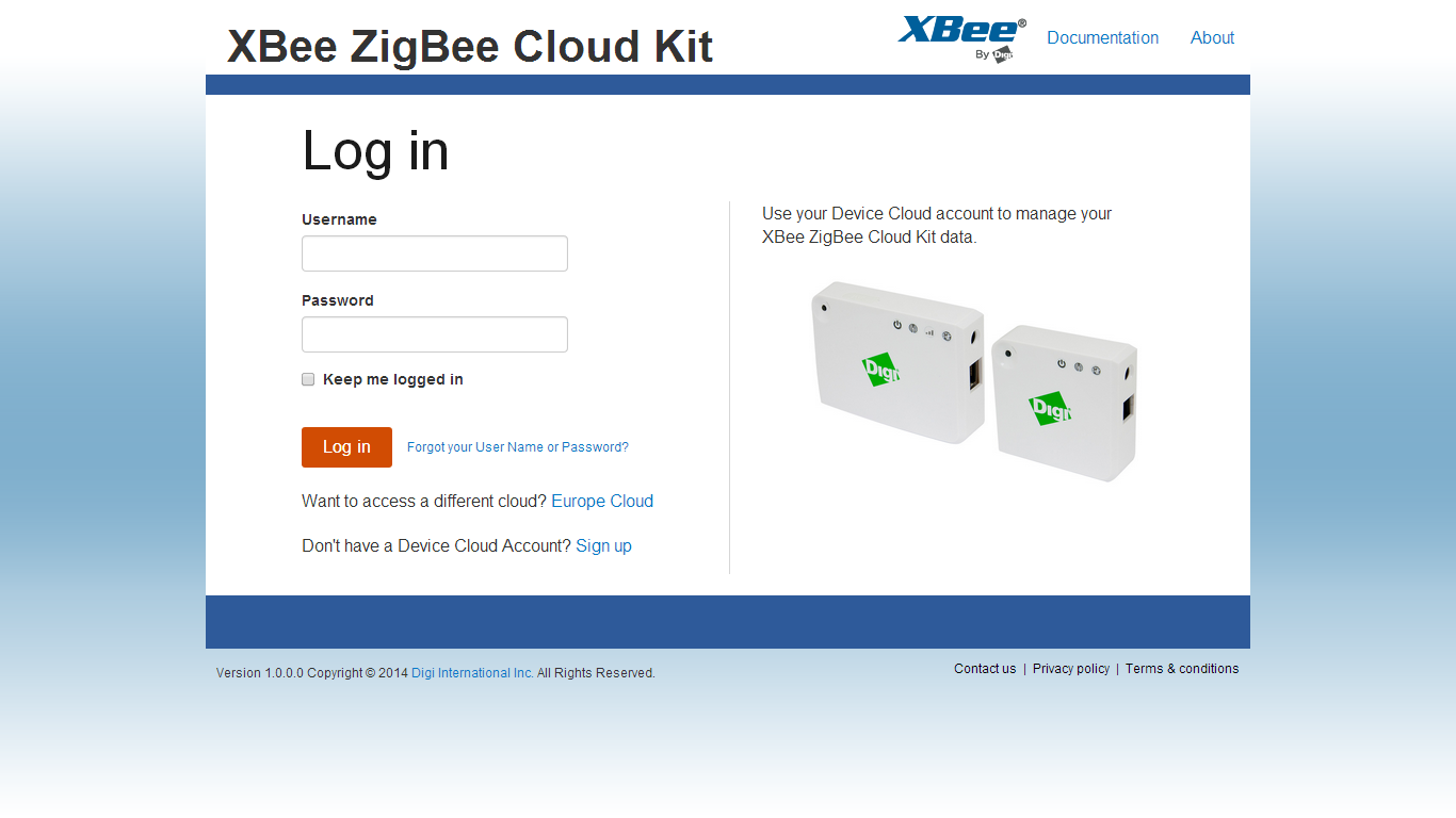
You will use the Digi XBee Zigbee Cloud Kit's web application to configure a widget for viewing the potentiometer readings: https://xbeegateway.herokuapp.com/#/login
- Log in to the Digi XBee Zigbee Cloud Kit web application.
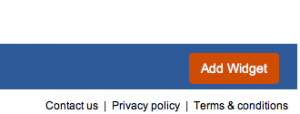
- Use the Add Widget button to create a new display widget.
- Choose Gauge Widget for the widget type.
- Add a label such as "Potentiometer."
- Choose your Digi XBee Zigbee device by its ID.
- Select ADC1 as the input stream and check the device configuration to make sure it is configured properly.
- Enter "value/2500*100" to transform the input from millivolts to a simple percentage from 0 to 100. The calculation takes the input value, scales to a decimal, then multiplies by 100 to get a percentage value. While the base value is 2500, you may want to adjust this number to properly calibrate it with your individual potentiometer.
- Add a name for Units such as "percent."
- Set a low value of 0 and a high of 100 to see the potentiometer range displayed.
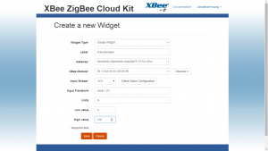
- Save the changes to see your new Widget.
6) Use it!
Your potentiometer settings are now instantly transmitted to the web. You can turn the knob directly to affect the gauge, and the new setting will be maintained until the knob gets moved again. This is terrific for testing out new circuits, but potentiometers can also be used to control an online setting, monitor anything that rotates, or as an input to a game that joins the physical and virtual worlds together. Once you're satisfied that your prototype creation is working well, try replacing the pot with a light or temperature sensor to create an input that reacts to real-world environments.
Read more about Digi XBee, >>.