Do you want to detect when a person passes by? Whether it is outside your apartment or your room or even in the next cubicle, you can now wirelessly detect if someone passes by which will sound a voice message and display a message on an LCD screen. This will use the Arduino microcontroller and XBee radio. After all, Arduino and XBee are best friends in the electrical engineering world! Why else would an XBee shield exist?
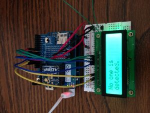 Nobody is detected
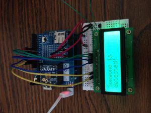
Somebody is detected!
Parts:
- Two solderless breadboards (MS MKKN2, AF 64, DK 438-1045-ND, SFE PRT-09567)
- One XBee radio (Series 2/ZB firmware) configured as a Zigbee Coordinator AT mode (Digi: XB24-27WIT-004, DK 602-1098-ND)
- One XBee radio (Series 2/ZB firmware) configured as a Zigbee Router AT mode (Digi: XB24-27WIT-004, DK 602-1098-ND)
- One Arduino Uno board (MS MKSP4, SFE DEV-09950, AF 50)
- Hookup wire or jumper wire kit (MS MKSEEED3, AF 153, DK 923351-ND, SFE PRT-00124)
- USB A-to-B cable for Arduino (AF 62, DK 88732-9002, SFE CAB-00512)
- XBee USB serial adapter (XBee Explorer or Digi Evaluation board) (AF 247, SFE WRL-08687)
- One XBee shield (Seeed Studio SLD01103P, Arduino A000065, SF WRL-10854)
- Wire strippers (AF 147, DK PAL70057-ND, SFE TOL-08696)
- One 16x2 character LCD display (with HD44780 parallel interface) (AF 181, DK 67-1758-ND, SFE LCD-00255)
- One 10K ohm potentiometer (panel mount) (DK P3C3103-ND, RS 271-1715, SFE COM-09288)
- One 300 ohm resistor (DK P300BACT-ND)
- 16-pin single-row male header (DK S1012E-36-ND, SFE PRT-00116)
- One XBee breakout board with male headers and 2 mm female headers installed (AF 126 (add SFE PRT-0016), SFE BOB-08276, PRT-08272, PRT-00116)
- PIR Motion Sensor (Parallax 910-28027)
- 9V Recording Module (RS 276-1323)
- One plastic board (roughly 4”x6”) (any hardware store will have this in some form)
- Soldering tools (any hardware store)
- A curious mind
Using the Arduino IDE
This project uses the Arduino software, known as the IDE, in order to program the Arduino Uno microcontroller. You can download it for free from the Arduino website software section at http://www.arduino.cc/en/Main/Software. There are many versions, so be sure to download the correct one. A basic guide to how to use it can be found at http://arduino.cc/en/Guide/HomePage.
Prepare and Configure your Coordinator Radio
- Use X-CTU to set the designated coordinator radio in API mode.
- Configure the coordinator radio with a PAN ID (between 0x0 and 0xFFFFFFFFFFFFFFFF). Make sure you note this ID so that you can set up your router radio with the same one.
- Enter in the High and Low destination addresses of your router radio.
Prepare and Configure your Router Radio
- Use X-CTU to set the designated router radio in AT mode.
- Configure the router radio with the PAN ID you set the coordinator radio with.
- Set JV to 1 to ensure that your router attempts to rejoin the coordinator on startup.
- Enter in the High and Low destination addresses of your coordinator radio.
- Set pin 11 (Digital pin 4) to mode 3, which is digital input mode.
- Set the sampling rate to 0x64 (100 samples per second).
Construct the Motion Sensor-XBee Connection
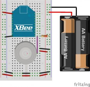
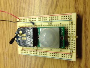
- Attach the XBee router radio to the breakout board, and then insert it carefully into the breadboard towards the top as shown in Figure 1.
- Connect XBee pin 1 to the power rail on the breadboard.
- Connect XBee pin 10 to the ground rail on the breadboard.
- Connect the power and ground on one side of the breadboard to the other side using jumper wire or the metal leads cut off from resistors.
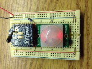
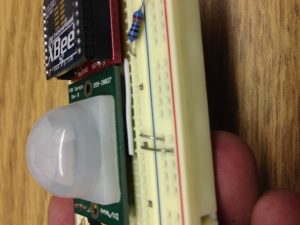
- Insert pins into the motion sensor as shown in Figure 2, and then insert the buzzer onto the center of the breadboard under the XBee as shown in Figure 1.
- Connect the sensor’s pin 1 to XBee pin 11.
- Connect a 300 ohm resistor from XBee pin 11 to the ground rail on the breadboard.
- Connect the sensor’s pin 2 to the power rail on the breadboard.
- Connect the sensor’s pin 3 to the ground rail on the breadboard.
- Hook up two AA batteries together and connect their positive and negative terminals to the power and ground rails on the breadboard respectively.
Construct the Security Monitor
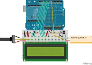 Figure 3
- Insert your Coordinator XBee Radio onto the XBee shield, and then insert the shield onto the Arduino board.
- Hook up the Arduino ground to the breadboard ground.
- Hook up the Arduino 5 volt supply to the power supply on the breadboard.
- Connect the power and ground on one side of the breadboard to the other side using jumper wire or the metal leads cut off from resistors.
- Trim the male headers down to 16 pins and then solder the row of male headers into the LCD screen.
- Insert the LCD onto the edge of the breadboard.
- Connect the LCD pin 1 to the ground rail on the breadboard.
- Connect the LCD pin 2 to the power rail on the breadboard.
- Attach the potentiometer to the breadboard next to the LCD screen. There are three pins: two terminals (the ends) and a wiper pin (the middle). Connect one terminal of the potentiometer to power and the other to ground (it doesn’t matter which). Connect the wiper (the center pin) to the LCD pin 3.
- Connect the LCD pin 4 to the ground rail on the breadboard.
- Connect the LCD pins 5, 6, 11, 12, 13, and 14 to Arduino digital pins 13, 12, 11, 10, 9, and 8 respectively.
- Connect the LCD pin 15 to the power rail on the breadboard.
- Connect the LCD pin 16 to the ground rail on the breadboard.
Next we’ll focus on the recording module segment of the security monitor:
This example uses a recording module from radio shack. By holding the white button, you can record a message up to twenty seconds long. Then, when you press the gray button (already removed in figure 4) it will replay the message. You can press it again to stop the message. The first step will be to remove the gray button carefully by unhooking it from the bottom. When you have done so, you will see two segmented lines in the shape of a circle. Looking at the circle geared towards the bottom, the left end is ground, and the right end is power. When these two lines are connected, the recorded message then plays. Our goal for this is to play a message of your choice when someone is detected by your security monitor (like a warning). Refer to Figures 4 and 5.
- Take two jumper wires on solder one wire to each segmented line.
- Place the 2N3904 transistor on the breadboard (preferably towards one end). Connect the middle terminal to digital pin 7 on the Arduino.
- When facing the transistor on the flat side, hook the left pin to the breadboard ground. Also, connect to the playback ground.
- Connect the right end of the transistor to the playback power.
- Record a message of your choice (no longer than 20 seconds).
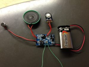 Figure 4
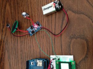 Figure 5
Program the security monitor
*when uploading the program to the Arduino board, make sure you switch the TX (connected to pin 1 on Arduino) on the XBee off. This can be done on the XBee shield.*
Upload the following program to the Arduino controlled security monitor:
#include <LiquidCrystal.h>
#include <WString.h>// connect to an LCD using the folowing pins for rs, enable, d4, d5, d6, d7
LiquidCrystal lcd(13, 12, 11, 10, 9, 8);// defines the character width of the LCD display
#define WIDTH 16
#define VERSION "1.02"int MESSAGE = 7;
int motion = 0;
void setup() {
pinMode(MESSAGE, OUTPUT);
lcd.begin(WIDTH, 2);
lcd.clear();
lcd.print("SECURITY");
lcd.setCursor(0,1);
lcd.print("MONITOR");
delay(2000);
Serial.begin(9600);
}
void loop() {
if (Serial.available() >= 22) {
if (Serial.read() == 0x7E) {
//read variable that we're not using out of the buffer
for (int i = 0; i<19; i++) {
byte discard = Serial.read();
}
motion = Serial.read();
}
}
motion = motion & B00010000;
if (motion) {
digitalWrite(MESSAGE, HIGH);
lcd.clear();
lcd.print("Someone is");
lcd.setCursor(0,1);
lcd.print("detected!");
}
else {
digitalWrite(MESSAGE, LOW);
lcd.clear();
lcd.print("No one is");
lcd.setCursor(0,1);
lcd.print("detected.");
}
delay(20);
}