Are you having a party? Would you like to be able to wirelessly control your disco ball’s revolution speed from afar? Then your solution is here! This project uses a set of XBees and an Arduino to control a disco ball’s lighting as well as how fast it revolves.
Parts:
- Two solderless breadboards (MS MKKN2, AF 64, DK 438-1045-ND, SFE PRT-09567)
- One XBee radio (Series 2/ZB firmware) configured as a Zigbee Coordinator AT mode (Digi: XB24-27WIT-004, DK 602-1098-ND)
- One XBee radio (Series 2/ZB firmware) configured as a Zigbee Router AT mode (Digi: XB24-27WIT-004, DK 602-1098-ND)
- One Arduino Uno/Leonardo board (MS MKSP4, SFE DEV-09950, AF 50)
- Hookup wire or jumper wire kit (MS MKSEEED3, AF 153, DK 923351-ND, SFE PRT-00124)
- USB A-to-B cable for Arduino (AF 62, DK 88732-9002, SFE CAB-00512)
- XBee USB serial adapter (XBee Explorer or Digi Evaluation board) (AF 247, SFE WRL-08687)
- One XBee shield (Seeed Studio SLD01103P, Arduino A000065, SF WRL-10854)
- Wire strippers (AF 147, DK PAL70057-ND, SFE TOL-08696)
- One 100K ohm resistor (DK P100KBACT-ND)
- One 200K ohm resistor (DK P200KBACT-ND)
- One XBee breakout board with male headers and 2 mm female headers installed (AF 126 (add SFE PRT-0016), SFE BOB-08276, PRT-08272, PRT-00116)
- Potentiometer: can be slide, thumbwheel, joystick, etc. This example uses rotational knob
- 4.5 V Disco Ball (Party City)
- Soldering tools (any hardware store)
- A curious mind
Using the Arduino IDE
This project uses the Arduino software, known as the IDE, in order to program the Arduino Uno microcontroller. You can download it for free from the Arduino website software section at
http://www.arduino.cc/en/Main/Software. There are many versions, so be sure to download the correct one. A basic guide to how to use it can be found at
http://arduino.cc/en/Guide/HomePage.
Prepare and Configure your Coordinator Radio
- Use X-CTU to set the designated coordinator radio in API mode.
- Configure the coordinator radio with a PAN ID (between 0x0 and 0xFFFFFFFFFFFFFFFF). Make sure you note this ID so that you can set up your router radio with the same one.
- Enter in the High and Low destination addresses of your router radio.
- Set pin 20 mode 2, which is analog mode.
- Set the sampling rate to 0x64 (100 samples per second).
Prepare and Configure your Router Radio
- Use X-CTU to set the designated router radio in API mode.
- Configure the router radio with the PAN ID you set the coordinator radio with.
- Set JV to 1 to ensure that your router attempts to rejoin the coordinator on startup.
- Enter in the High and Low destination addresses of your coordinator radio.
- Set the sampling rate to 0x64 (100 samples per second).
Construct the XBee-Potentiometer connection
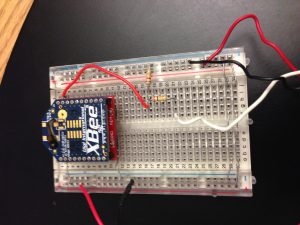 Figure 1
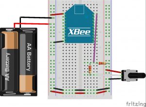 Figure 2
- Attach the XBee coordinator radio to the breakout board, and then insert it carefully into the breadboard towards the top as shown in Figure 1.
- Connect XBee pin 1 to the power rail on the breadboard.
- Connect XBee pin 10 to the ground rail on the breadboard.
- Connect the power and ground on one side of the breadboard to the other side using jumper wire or the metal leads cut off from resistors.
- Connect the potentiometer knob power to the breadboard power rail and the knob ground to the breadboard ground rail.
- Connect the other wire/middle pin to a spot on the breadboard. From there, connect a 200K ohm resistor.
- Connect the opposite side of the resistor to XBee pin 20.
- Connect a 100K ohm resistor from XBee pin 20 to the ground rail on the breadboard.
- Hook up two AA batteries together and connect their positive and negative terminals to the power and ground rails on the breadboard respectively.
Construct the XBee-Arduino-Disco Ball Connection
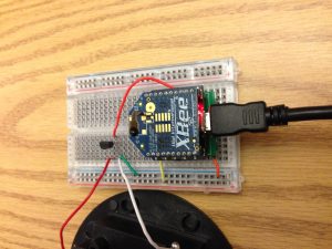
Figure 3
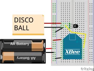
Figure 4
-
- Attach the XBee router radio to the XBee Arduino stacker, and then insert it carefully into the breadboard towards the top as shown in Figure 1.
- Connect pin 1 to the power rail on the breadboard.
- Connect pin 10 to the ground rail on the breadboard.
- Connect the power and ground on one side of the breadboard to the other side using jumper wire or the metal leads cut off from resistors.
- Gently unscrew the top cover off the disco ball’s base. Depending on your specific Disco Ball brand, this may disconnect the ball from the motor. When the cover is off (you likely have to cut if off), reconnect the ball to the motor.
- Locate the two wires connected to the switch. Desolder them from the switch. You should now have an open switch like that of figure 3. To ensure that you did everything right, connect the wires together (don’t solder!) like in Figure 4. If the disco ball lights up and spins, you are golden to continue on. Pull the wires apart again.
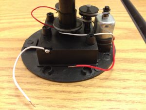 Figure 5
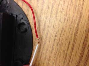 Figure 6
- Place the 2N3904 transistor on the breadboard (preferably towards one end). Connect the middle terminal to digital pin 6 on the Arduino.
- When facing the transistor on the flat side, hook the disco ball ground wire to the left pin. Connect it to the breadboard ground, too.
- Hook the disco ball power wire to the right pin.
- Hook up two AA batteries together and connect their positive and negative terminals to the power and ground rails on the breadboard respectively.
Program the Arduino
*when uploading the program to the Arduino board, make sure you switch the TX (connected to pin 1 on Arduino) on the XBee off. This is not necessary for the XBee stacker, though.*
Upload the following program to the Arduino microcontroller:
// Disco Ball
int analogValue = 0;
void setup() {
pinMode(6, OUTPUT);
Serial1.begin(9600);
}
void loop() {
// check that the buffer has everything
if (Serial1.available() >= 21) {
// search for the start byte
if (Serial1.read() == 0x7E) {
//read variables that we're not using out of buffer
for (int i = 0; i<18; i++) {
byte discard = Serial1.read();
}
int analogHigh = Serial1.read();
int analogLow = Serial1.read();
analogValue = analogLow + analogHigh * 256;
analogWrite(6, analogValue/4);
delay(10);
}
}
}