Table of Contents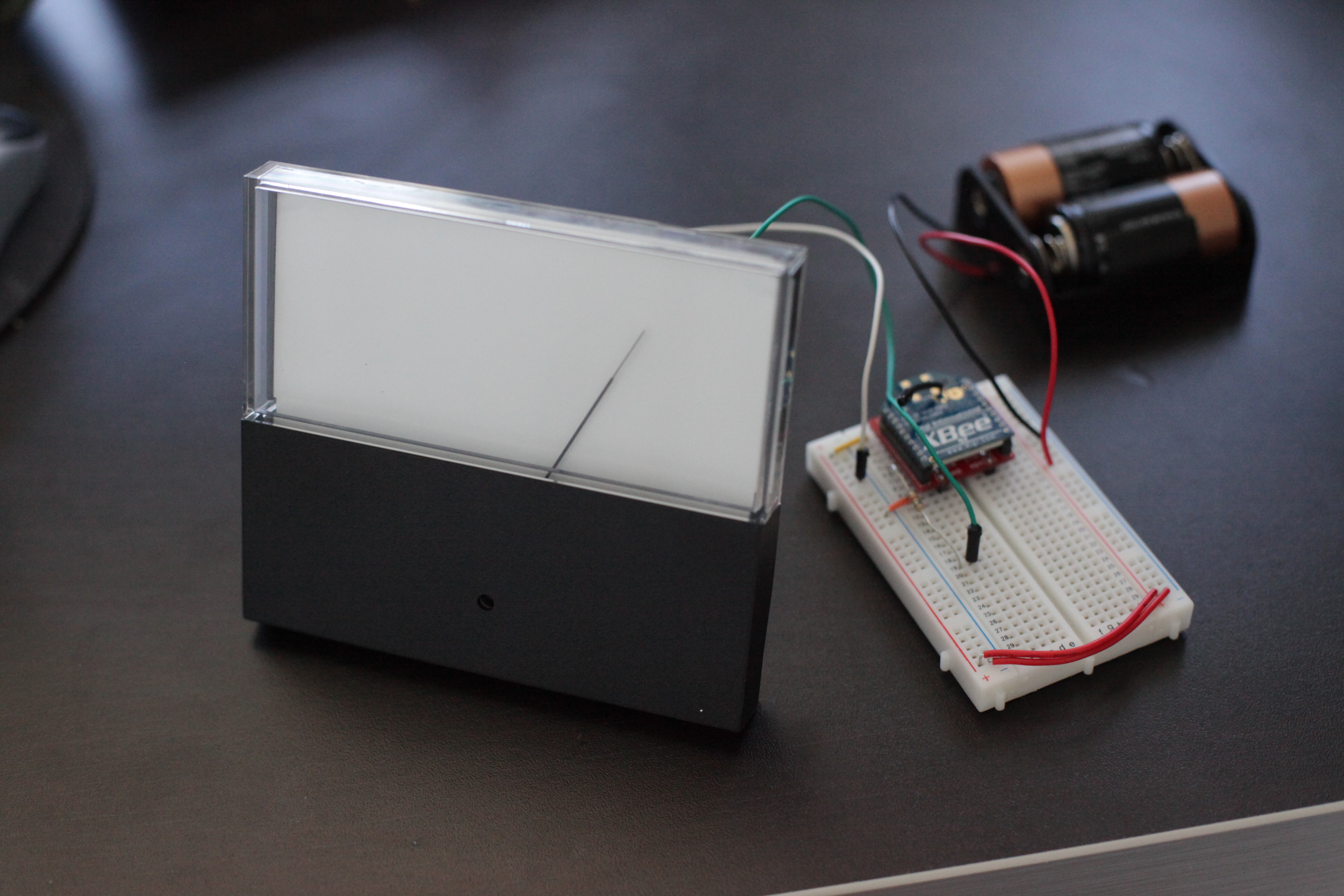
- Introduction
- Assemble the Parts
- Configure the Radio
- Wire up the Circuit
- Use it!
1) Introduction
As the world of technology becomes increasingly digital, the nostalgia for older analog technology grows. The panel meter is a great piece of analog technology that can be easily integrated into your projects. And thanks to the XBee 802.15.4 radio's digital to analog converter, you can make a wireless panel meter with only a few components.
2) Assemble the Parts
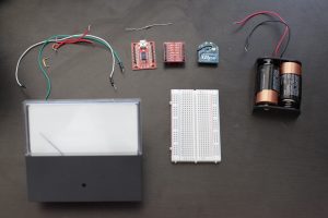
To hook up a LED to an XBee for PWM output, you'll need:
- XBee 802.15.4 Radio
- Panel meter - We're using a 0-1mA DC ammeter from All Electronics
- Resistor - 15k ohms if you're using a 0-1mA DC ammeter
- Breadboard
- Jumper cables
- XBee Breakout Board - for your circuit.
- XBee Explorer USB - for programming your radio.
- A DC power source, 2.8 - 3.3V - We'll be using two C batteries in a battery holder from Radio Shack.
4) Wire up the Circuit
- Place the XBee adapter into the breadboard.
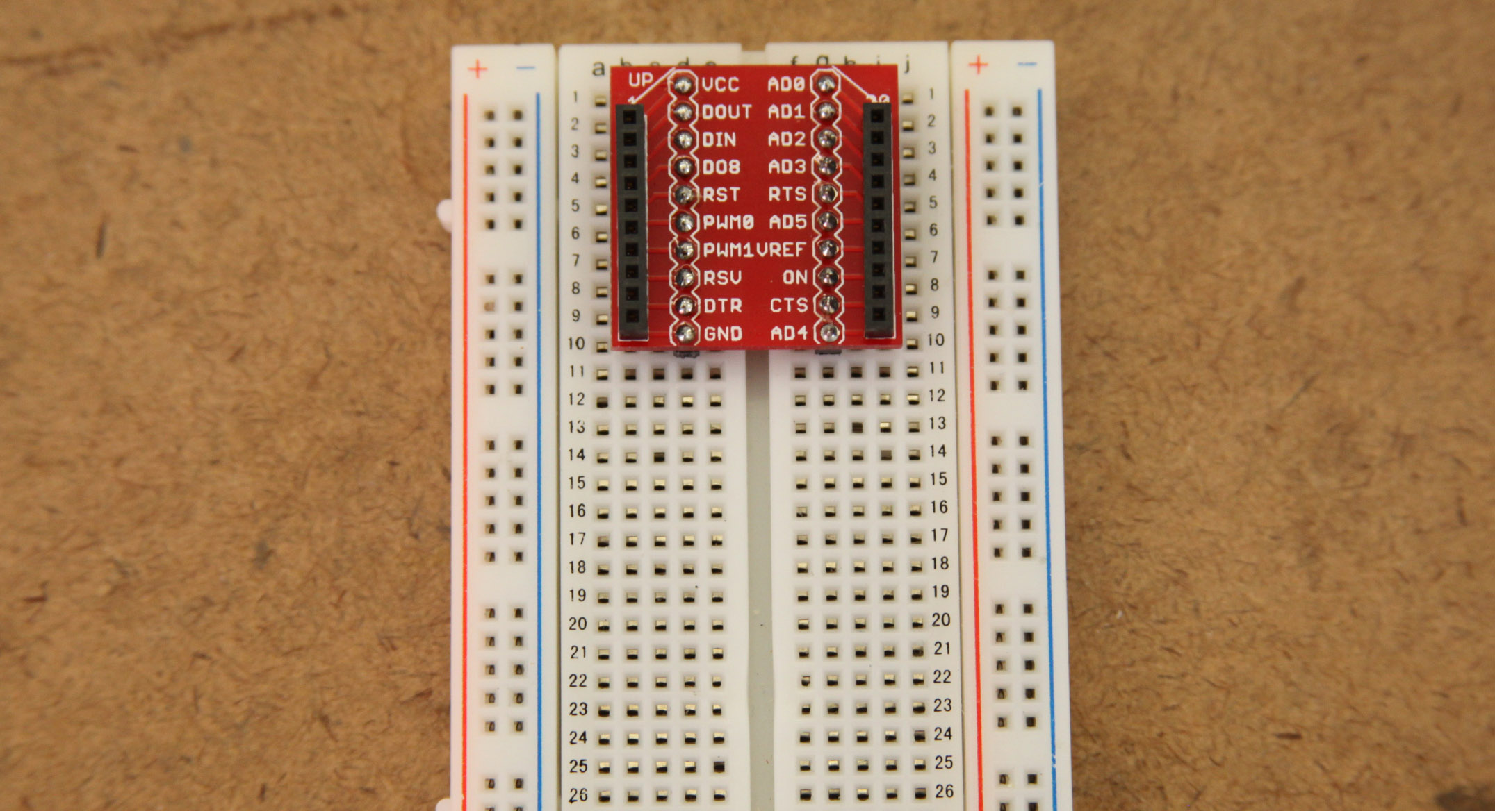
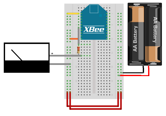
- Connect the VCC terminal of the XBee adapter to the positive rail and the ground terminal to the negative rail.
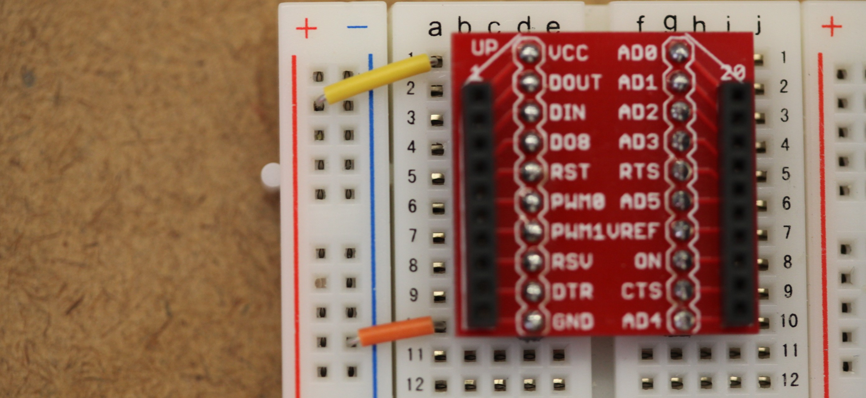
- Connect + terminal of the panel meter through a 15k resistor to the PWM0 pin of the XBee breakout board, which is the 6th pin down on the left side. Connect the other terminal of the panel meter to ground.
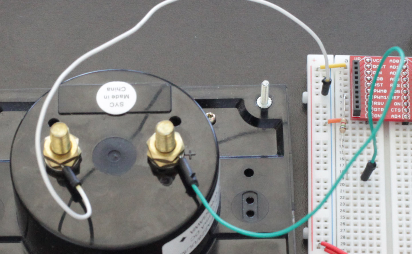
- Insert the XBee into the breakout board and connect the power source.
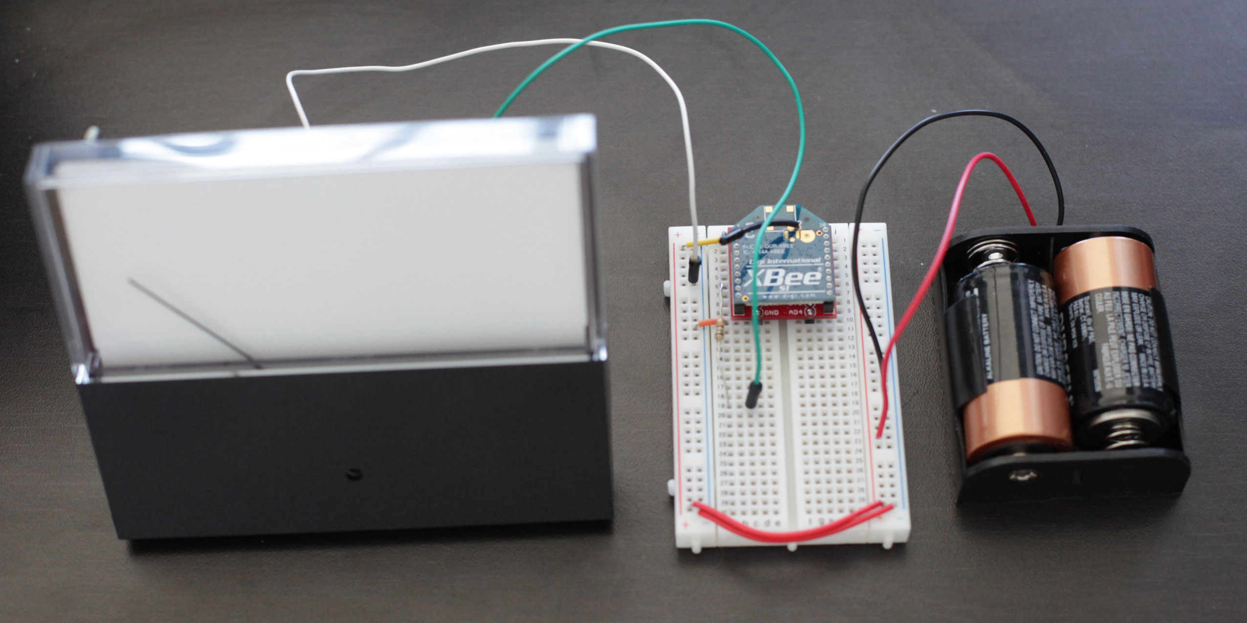
- Your circuit should look something like the diagram above.
5) Use it!
Now that you know how to connect a panel meter to the PWM output of an XBee radio, take a look at our input tutorials for what can move the needle. Just be sure that the the transmitter's address is set as the receiver's I/O input address setting (ATIA). The video above shows a wireless light sensor connected to a wireless panel meter.