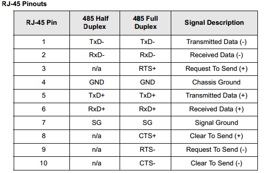
RJ45 10 pin (4 wire)
Two wires (one twisted pair) are required for each signal, a positive lead ("+"), and a negative lead ("-"). The "+" leads at one end of the cable must
be connected to the "+" leads at the other end, and the "-" leads at one end must be connected to the "-" leads at the other end.
Incorrect wiring could result in damage to the connected devices. The following tables show the pin configurations for the EIA-485 versions of
Digi RJ-45 10 pin connectors.
*Note: Four wire (full-duplex) wiring requires the use of a 10-pin RJ50 connector with the exception of the models offering the software selectable MEI Serial Settings, the Alternate 4-wire option will work with 4-wire (full-duplex) and 8-pin connectors/cables:


When wiring with a 10 pin RJ50 cable connector you do not need to tie 1 & 2, and 5 & 6 together, this is done internally in the PortServer. You need to pick either 1, or 2, and 5 or 6. It is also necessary to wire GND.
RJ45 8 pin (2-Wire)
If an 8 pin Rj45 connector is being used the pins will shift one position:
Pin 1: – (minus) signal
Pin 2: NA
Pin 3: GND
Pin 4: + (plus)signal
Pin 5: Other+ (plus) signal
Pin 6: SGND
7 & 8: Not used
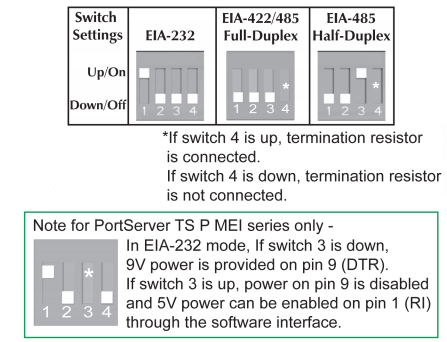
You may also need to enable the 4th switch of the dip switch (up position) to enable termination for the RS485 line.
Dip Switch Settings
Software Configurable Models
To configure MEI settings on units with software configurable settings rather than dip switches, navigate to the serial port MEI settings in the web interface:
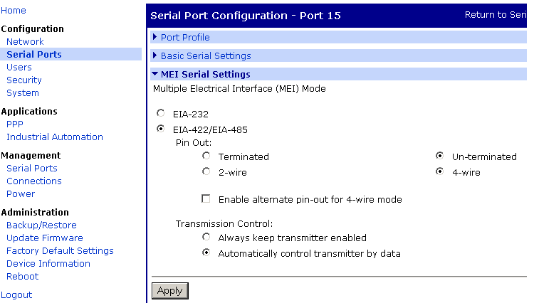
Set termination as necessary. The always keep transmitter enabled setting should be on if you are using an external 4 wire to 2 wire converter.
Last updated:
Jan 04, 2024